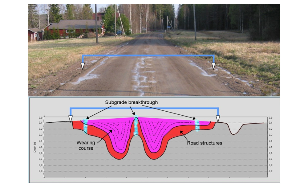
9.1. General
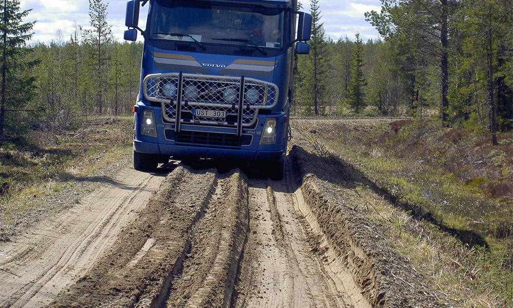
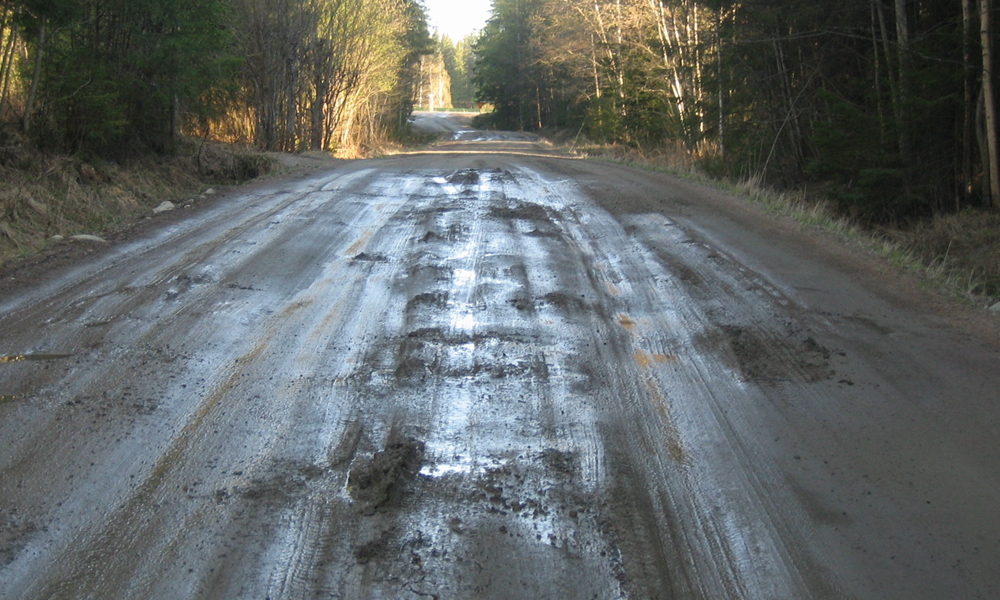
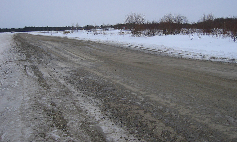
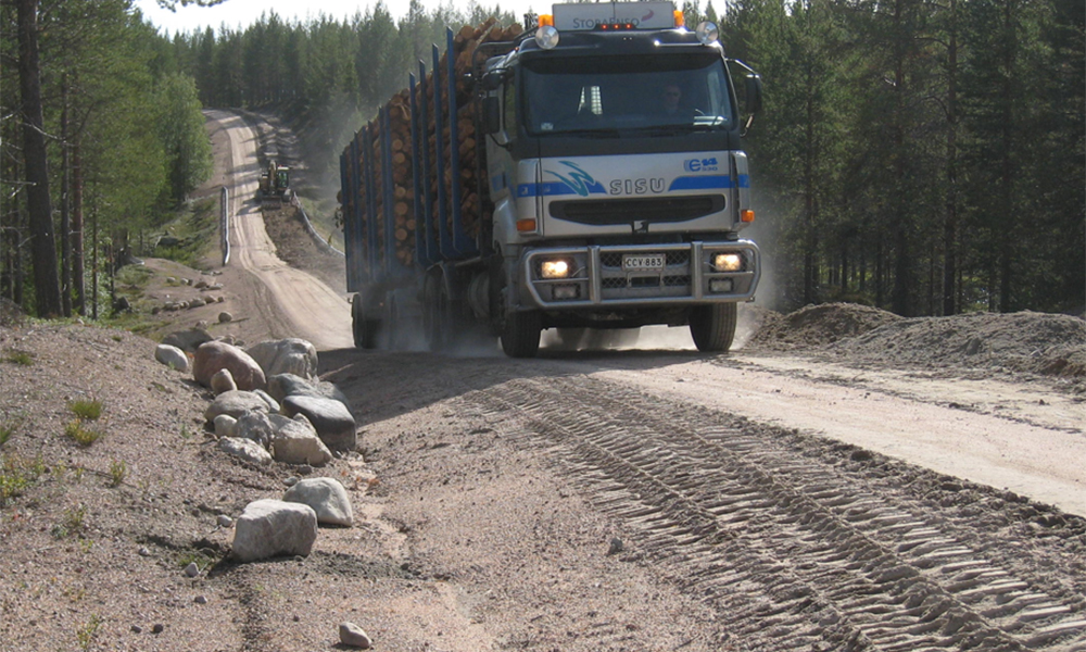
Renovation, rehabilitation, strengthening or improvement of gravel road or forest road structures should be carried out where the structural and/or functional condition of the roads has become so poor that it is preventing economical and safe driving and transport on the road. On gravel roads and forestry roads, this should be done thoughtfully and only in areas where it is necessary. Load restrictions or even road closures are also possible options, but these should be done without causing accessibility problems or another unnecessary harm to local livelihoods.
Renovation can be divided into four phases: 1) road diagnostics, 2) renovation design, 3) carrying out the renovation, and 4) quality control and documentation. And once the renovation has been executed, there should be some form of follow up of the performance of the renovated structures to add to the continuous learning process.
This chapter will describe in brief the basic principles and processes for renovation projects on gravel and forest roads. More detailed theory and information about the renovation design and structures can be also found in the ROADEX eLearning packages on “Permanent Deformation”, “Drainage” and “Roads on Peat” at https://www.roadex.org/e-learning/lessons/
In addition ROADEX has also published several reports on spring thaw weakening and forest road rehabilitation that can be found at: https://www.roadex.org/services/knowledge-center/publications/
9.2. Road diagnostics
Very often both gravel and forest road renovation design is made based only on a visual overview of the road and the resulting design based on the experience. The main reason for this is that it is generally understood that modern diagnostics surveys are too expensive for gravel roads and that the money would be better spent on “real construction”. This assumption however is not borne out in practice. ROADEX tests on forest roads in Sweden and Finland have shown that project total costs can be lower on forest road renovation projects if the design is made based on measured facts and exactly on the correct spots compared to project using visual design. In addition life cycle costs can be much lower. Finally, in many countries there are a limited number of experienced designers of gravel road or forest road renovation projects and this is why clear rules for diagnostics based renovation design are needed in the future.
The most important issue when starting the renovation process of a gravel or forest road is to define the root cause of the problems taking place in the road. In low volume roads this can be related to the risk analysis, i.e. the main risk for road failures. Mike Pinard has classified five main risks for rural road problem in Africa, and this can be a very useful method also for gravel and forest roads in the ROADEX area and elsewhere:
- Material quality ( strength, durability, moisture sensitivity)
- Drainage (dewatering, drainage)
- Construction control (compaction, layer thickness)
- Maintenance ( wearing course, drainage, winter maintenance)
- Traffic (overloading)
If one of these risks is realized the single risk can normally be handled with maintenance, but if two or more risk categories are identified then there will be most likely major failures that will require renovation or rehabilitation.
This simple diagnostics categorization does not however help to define the optimum renovation structure for each issue. For this the ROADEX rutting mode classification is also needed as most of the problems in gravel and forest road can be related to permanent deformations.
Survey technologies and their diagnostics for gravel and forest roads have already been described in the other chapters of this eLearning package. This chapter instead will focus on recommended ‘fit for purpose’ solutions for typical problems in these roads.
9.3. Renovation design
9.3.1. Design process
The renovation design process for gravel and forest road is basically the same, but on forest roads, where the service level does not have to be the same for the whole road, there can be more options. Harvesting operations can be designed to avoid road sections that are too expensive to be strengthened for year round work. The renovation design steps, and details of each step, are described below:
- Collection and analysis of existing material
- New survey data collection, data processing and analysis
- Problem diagnosis
- Sectioning the road into homogenous sections
- Decision of the renovation / bearing capacity target level
- Sectioning the road for different renovation classes
- Calculation of design parameters (E2, layer modulus, etc)
- Selection of renovation techniques / structures
- Design of new structures and their materials
- Road geometry design
- Drainage solutions
- Volume/mass counting and costs
- Preparation of work specifications
- Printing the plan
1. Collection and analysis of existing material
A project should always start with the collection of all existing data available from the road. This should include old design documents if available, acquiring general information of the area such as topography and soil maps and aerial photos, available lidar data, environmental protection areas/spots and information of any existing aggregates available.
2. New survey data collection, data processing and analysis
ROADEX recommends comprehensive data collection and analysis for forest road and gravel roads because this objective data is the only way to be able to prepare ‘fit for purpose’ renovation solutions for the roads. Such solutions will be always cheaper than whole road renovations as investments will not be needed on existing good road sections. Possible survey technologies are described in detail in other chapters of this eLearning package.
3. Problem diagnosis
Problem diagnosis is made based on the data collected in Step 1 and 2, i.e. existing information and new survey data. All further renovation design decisions will be based on this diagnosis and the on the level of difficulty of each problem.
4. Sectioning the road into homogenous sections
In the road sectioning step the road is divided into homogenous sections with one specific renovation technique to be used in the section. There are no specific lengths for sections but the rule of thumb is that the more expensive the renovation structure, the shorter the section should be. A good example of this is a culvert or soil replacement structure that can be as short as only tens of metres.
5. Decision of the renovation / bearing capacity target level
The budget for a renovation project will depend totally on the problem diagnostics and on the length of each section and on the selected bearing capacity target level. For this reason in this step it will be extremely critical to discuss the target level with the road owners or organization paying the bill. After the budget is known the renovation risk classes can be selected. Experience has shown that if design target is 0% risk for any of the risk classes the final budget will be very high. Normally minor risks can be accepted on 5-10% of the road length, but no major risks.
6. Sectioning the road for different renovation classes
First thing in sectioning for a gravel and forest road renovation design is to decide on the general renovation classes to be used. The classes recommended by ROADEX are: I Basic structure (BS), II Steel grid (SRI), III Raising the road alignment (RA), and IV Soil replacement (SR). These classes are described in detail later in Section 9.3.5 “Typical renovation structure classes for gravel and forest roads”.
In addition to this, the basic structure (BS) category should be divided into subsections to make the future lifetime of the road to be as homogenous as possible. In practice this means that thicker/stronger structures should only be designed for the weakest sections and the best existing sections given mainly “cosmetic” measures, or none at all. In order to do this there needs to be a system for calculating the current bearing capacity. This can be done by a) using measured surface moduli value E2 from FWD data or b) back calculating or forward calculating layer and subgrade moduli values and using the Odemark model for calculating surface bearing capacity or bearing capacity at each layer surface. The Odemark model is better model if layers, such as the wearing course, are to be removed during the strengthening. In addition DCP measurements could also be used in the design.
7. Calculation of design parameters (E2, layer modulus, etc)
Once the current bearing capacity and target bearing capacity are known, the next goal is to define the BS strengthening structure classes to be used in the project. This normally means rounding off the structure thickness to even numbers, such as 10 cm, 20 cm, 30 cm extra base course aggregate on the top, or in class SR shallow soil replacement 0.6-0.8 m or deep soil replacement 0.9-1.2 m. A further subclass could be used where surface homogenization is needed. Overall, the number of renovation classes/types should be limited on a project. ROADEX recommends a no more than 5-7 classes/subclasses should be used.
8.Selection of renovation techniques / structures
When selecting the renovation techniques and structures to be used in a project the most important things to clarify are the material types and machinery available. A good example of this would be what types of homogenization machinery there would be locally, i.e. are there crushing or mixmilling systems, or should the homogenization be done by excavator, or by excavator spike bucket, or both. In soil replacement options one of the key issues would be the availability of natural sand.
9.Design of new structures and their materials
Step 9 covers the location and design of the new structures based on the defined structure classes from step 7 and the material properties (moduli values) of the new materials to be used in the project (step 8). The structure class to be selected should be strong enough to meet the target bearing capacity level (knowing that 5-10% can be slightly below).
10. Road geometry design
Step 10 is a slightly different task from the previous steps as it deals with road sections with identified geometry issues. In practice this means mainly taking care of the road sections that are widening due to Mode 2 rutting problems or just poor maintenance. Other road geometry deficiencies should also be addressed at this time, e.g. tight curves and poorly designed intersections, as well as the length of passing places for longer trucks. This step should also check if the new road and ditches will still lie within the agreed road area.
11. Drainage solutions
Even though drainage design normally starts the renovation process, this step will allow a final drainage check to be carried out once the final grade line, road widths, geometry, any new and replaced culverts and their position are known. Drainage design principles are discussed in more detail in Section 9.3.3 “Drainage design”.
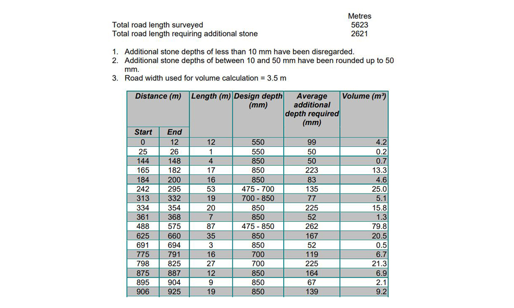
12. Volume/mass counting and costs
Once the design is ready Step 12 focuses on calculating the masses or volumes of the materials needed. In these calculations the following classes of materials are normally used.
- A. “Removed material”. This means material that will be excavated from the road structures or ditches to be stored in spoil deposits or similar areas.
- B. “New material”. This means mainly the new aggregate that will be transported to the site and used in the new structures.
- C. “Treated material”. This means thickness and volume of materials to be treated on the road. A good example of this is the homogenization of the road surface. This material will not increase the thickness of the road structure.
- D. “Geotextiles etc”. This means material such as geotextiles or steel grids that will used to strengthen the road. These do not increase the thickness of the structure. Culverts are also classified in this class.
- E. “Other measures” include operations such as clearing vegetation etc.
Once the total amount of these classes are known (tonnes, m3, m2, etc) and their unit prices when installed in the road structure, then the total cost estimate for the project can be calculated. The general overhead costs including quality control etc can then be added to get the final budget estimate for the project.
13. Preparation of work specifications
In this step general work descriptions with standard cross-section drawings should be prepared for each section defined in step 6.
14. Printing the plan
The final step covers preparing the documents ready to be printed or digitally documented to be used in the procurement process.
9.3.3. Drainage design
Every renovation project should start with drainage diagnostics and design. Other measures can be considered after that if there is money. This is because the cost benefits of drainage improvement are always better than any other measure.
Drainage design should focus the following objectives:
Main road culverts
Main road culverts should be first checked for their general condition (i.e. straight with no voids or openings) and that they are clear of mud or other material. They can also be checked if they are at the correct level and if they are causing frost bumps. If this is the case transition wedges should be designed. Local maintenance crews should be asked if they know of any culverts with icing problems. Finally a check should also be carried out to identify if any new culverts that need to be constructed (for instance if bedrock is close to road surface).
Access road culverts
Accesses should be checked for missing access road culverts that could cause problems for the main road. The general condition of access road culverts and their size (often too small) should be checked and that they are not filled with mud or other material. Check also that they are constructed at the correct depth and if local maintenance crews know of any culverts with icing problems.
Side ditches
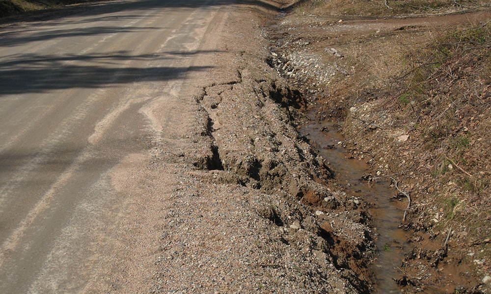
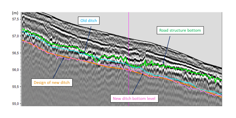
Side ditches should be checked that they are deep enough to keep the road structure dry, i.e. 20-30 cm deeper than the bottom of the road structure and that water can flow freely. If this is not the case the side ditch should be cleared and where necessary identified how much deeper they should be. In side ditch design the relative levels of the main road and access road culvert should be kept in mind and that the ditch depths match their level.
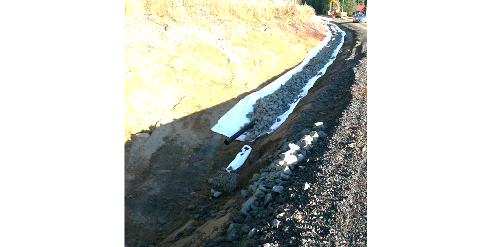
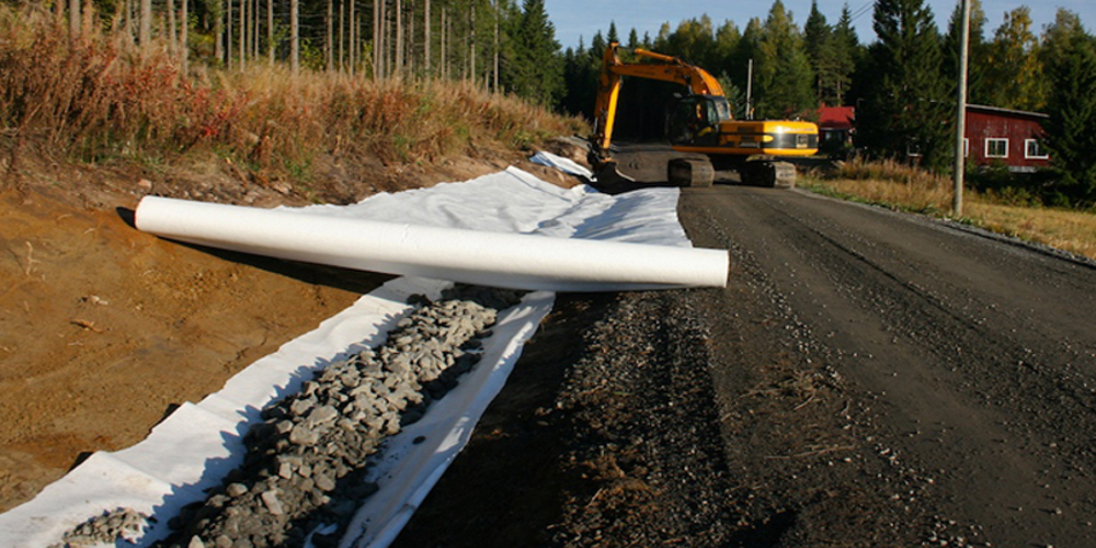
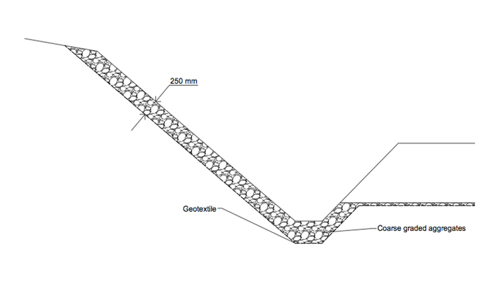
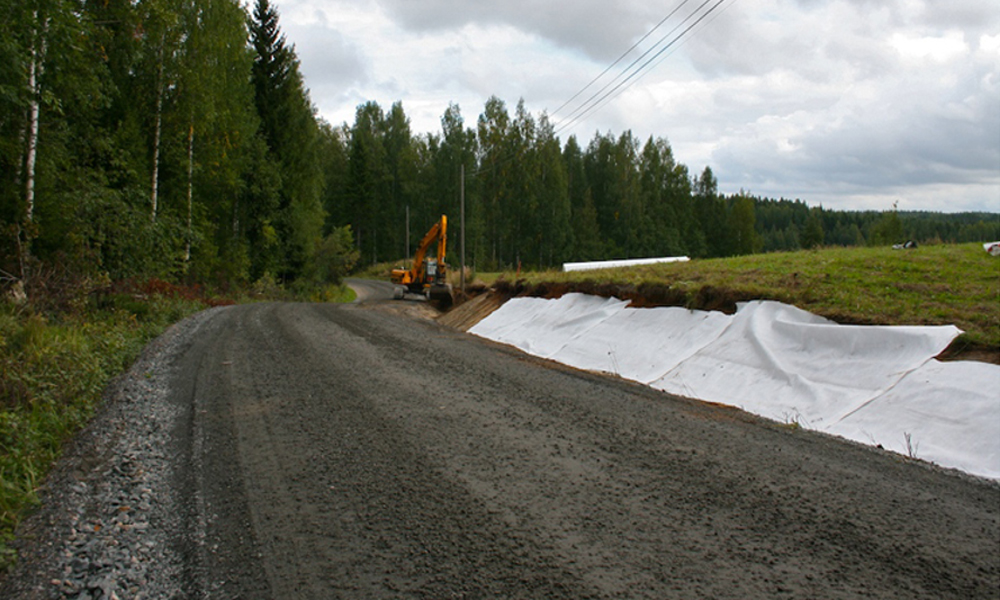
If the road is located on side sloping ground, and the side ditches regularly become filled, a support structure with subdrains can be used on the upper side of the road. This structure will also act as a support against shoulder deformation.
Side ditch support without subdrains can also be used where the outer slope has proven to be unstable but the road shoulder is strong enough.
Outlet ditches
Outlet ditches should be checked for general condition. If they are blocked with vegetation/debris the ditches should be scheduled to be re-opened. Keep in mind that these outlet ditches can be outwith the road area and if so it will be necessary to confirm with the land owner that the ditch opening can be done. If an outlet ditch cannot be constructed it may be possible to build infiltration wells.
Verges
In renovation design existing verges should be always removed. Their presence can be evaluated visually or they be measured with lidar and the sections listed in the design documents.
9.3.4. Bearing Capacity Design
There are many techniques that can be used to design bearing capacity for gravel and forest road renovation projects, most of which use tables or measured E2 values. The problem with all of these procedures is that it is difficult to estimate the bearing capacity properties of the current structures. Also, if it is decided to remove any problem layers from the surface, these systems do not take this into account. The ROADEX project has been testing the use of the Odemark design system for gravel and forest road renovation and recommends its use. The system is based on equivalent thickness calculation based on the stiffness of the materials.
In the Odemark method the increase in bearing capacity on the top of a structural layer, compared to the bearing capacity below the layer, is determined by both the layer thickness and modulus. This means that the bearing capacity on the top of the pavement structure is determined by the properties of the subgrade and each of the individual layers above the subgrade. The Odemark formula is a simple method for determining the bearing capacity of a layered structure. It does not take loading into account. The bearing capacity is calculated only on the basis of the thickness and the modulus of the layer. Nevertheless, the formula provides an easy way to evaluate if the structure is sufficiently stiff for the intended loadings on the road. The Odemark formula is well known and still very widely used in many countries for the structural design of roads. The formula is defined as follows:
When calculating the initial existing Odemark bearing capacity the moduli values from FWD and GPR data are used together with GPR thicknesses to create a continuous bearing capacity profile. This profile clearly indicates the weak sections of the road and also how weak they are compared to target bearing capacity.
The target level is then set as described in Step 5 and the different thickness and structure combinations are tested until the design bearing capacity meets the target bearing capacity value. Moduli values for the new material can be defined by their grain size distribution. Typical moduli values to be used in crushed 0-35 mm or 0-50 aggregates with good grading is 200 – 280 MPa.
The weakness of the Odemark system, as described earlier, is that on places with bedrock the calculated bearing capacity can be too high, and where this happens the analysis should also use SCI values and drainage condition for design. Many times the key problem with roads on bedrock sections is drainage.
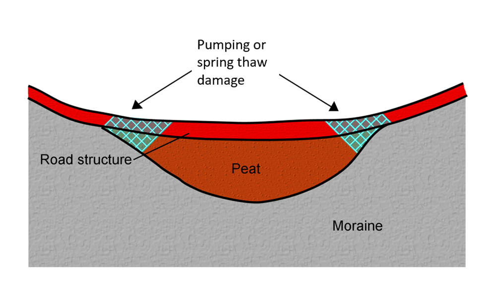
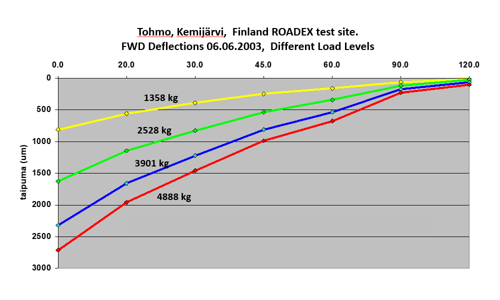
Another weakness with the Odemark system is that on roads built on peat the method can give values that are too low and in these sections the BCI classification should also be used. The rule of thumb is that if the central FWD deflection with a 50 KN load on a gravel or forest road built on peat is higher than 2000 µm, then the minimum layer thickness needed to get 90 MPa bearing capacity is about 0.5 m. If the deflection is more than 3000 µm, still more aggregates will be needed, but there will be a consequent risk for major settlements on the road. That is why steel grid structures are recommended for these sections as their effect equals at least 200 mm of new aggregates.
9.3.5. Typical renovation structure classes for gravel and forest roads
According to the ROADEX project recommendations gravel road and forest road renovation structures can be generally classified into four classes: I Basic structure (BS), II Steel grid (SRI), III Raising the road alignment (RA), and IV Soil replacement (SR). These classes were made originally for the design against spring thaw weakening damages but can be used in any renovation project of gravel and forest roads.
Additional details of each structure class, design cross section and work description are given in the following.
1. Basic structure, BS, “new layers on the top”
The “new layer on the top” option is the most common solution in the renovation of gravel and forest roads. Basically this means that the problem is fixed by adding new layers on the top of the existing road structure. However there are two very important measures in this structure that are often forgotten or ignored: a) the existing old wearing course material must be removed, and b) the condition and quality of the underlying layers should be known to determine if homogenization is required or not. This can done using test pits, GPR survey or other survey methods described in this eLearning package. In addition it should be checked that there are no boulders close to the surface. If there are indications of these problems the layers should be homogenized and boulders removed. If survey information is not available the layers should be homogenized.
The biggest problem especially with gravel roads is that the wearing course with high fines content is often left on the top of the road. With a forest road this is not such a big problem but on public gravel roads this water impermeable layer can easily cause a “sandwich structure” and the road may behave even worse after the renovation. The ROADEX project research against permanent deformation has showed that the minimum thickness of the base course should be 200 mm. Base course thicknesses of 100 mm are too thin.
BS “new layer on the top” working method description:
Removal of Old Wearing Course, Homogenization
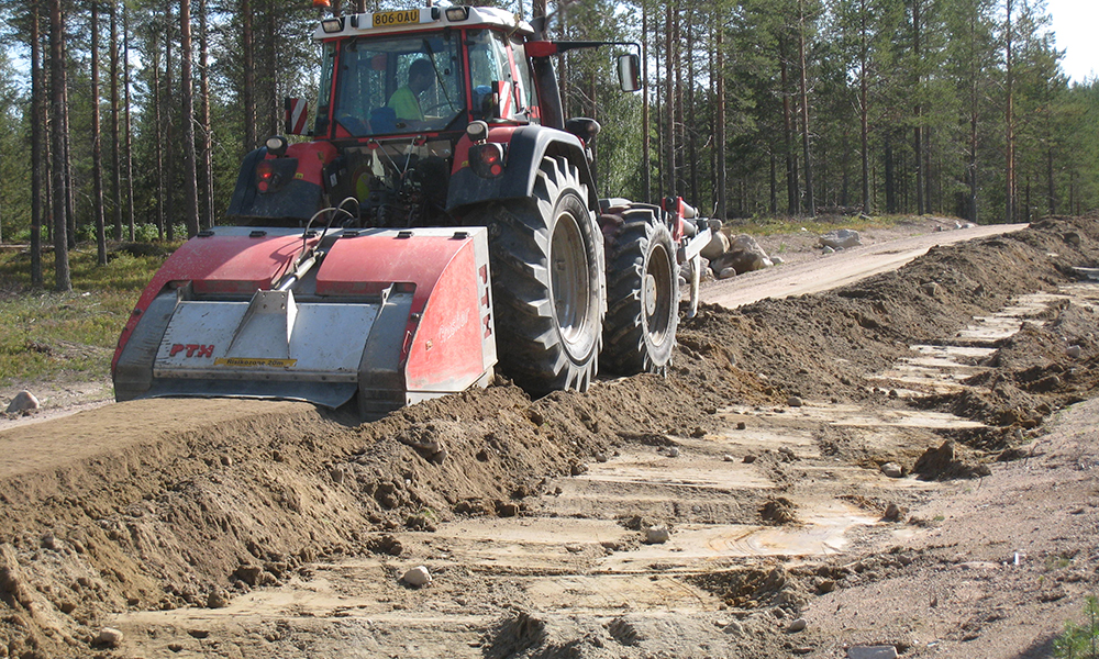
Renovation is started with the removal of the existing wearing course material to the depth of 50 – 150 mm from the road surface. Any old wearing course material should also be removed from the length of transition wedges. Wearing course material with high fines content should not be left under the new structure but it can be used later for the new wearing course material or on the road shoulders. After removing the old wearing course, the top 300 mm of the structure should be homogenized if needed. Homogenization is done in order to remove boulders and stones and create a homogenous platform for the new structure. Before placing the geotextile (filter cloth) the road should be shaped to the cross slope of 4% and compacted.
Filter Cloth, Base Course and Wearing Course
The geotextile is placed transverse to the road direction overlapping by at least 500 mm. The base course is laid over the geotextile and compacted. The base course thickness is normally 200 or 300 mm. The base course is shaped to the cross slope of 4% and 100 mm wearing course material is laid on it before being shaped again to the cross slope of 4%. If old wearing course material is to be re-used, a proportion design should be carried out with the new wearing course containing a maximum of 50% of old material. The transition wedges are reconstructed by shaping the base course material to a slope of 1:40, the wearing course is constructed to the full thickness of 100 mm. The geotextile (filter cloth) is not used in the transition structures.
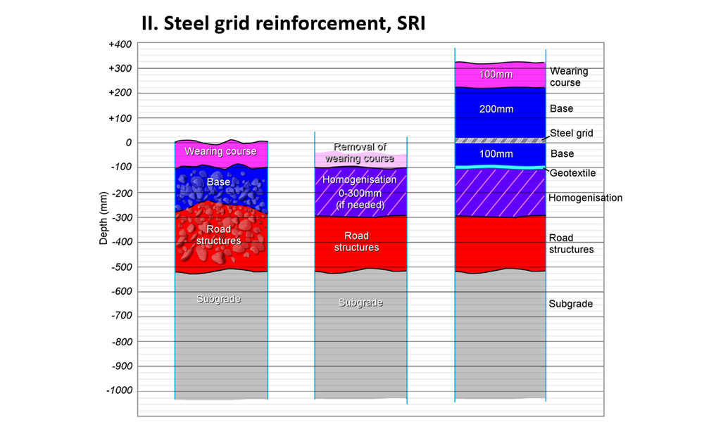
2. Steel reinforcement, SRI
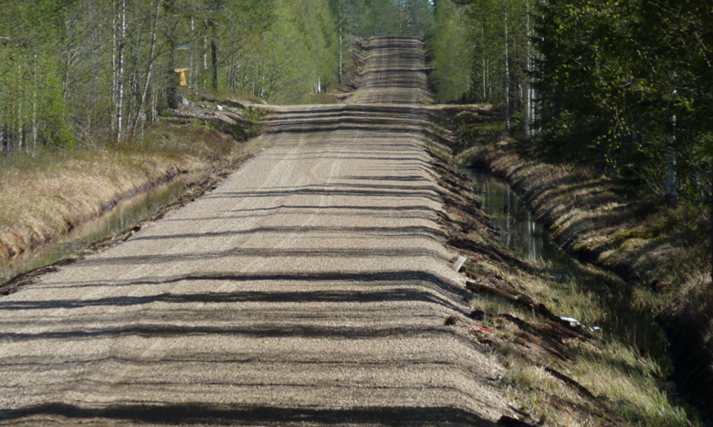
A steel reinforcement structure is recommended when strengthening a gravel or forest road resting on peat and suffering from severe Mode 2 rutting and/or pumping. This structure benefits from the high tensile strength of the steel grid. When installed at the optimum depth, and inside the base course with good interlocking with the base course stones, the combined structure can spread the loads of heavy trucks over a wider area.
SRI working method description:
Removal of Old Material
Renovation is started with the removal of the existing wearing course material to the depth of 50 – 150 mm from the road surface. The old wearing course material should also be removed from the length of any transition wedges. Wearing course material with high fines content should not be left under the new structure but it can be used later for the new wearing course material or on the road shoulders. After removing the old wearing course, the remaining 100 – 150 mm of the old material should be removed if the ground appears variable. Later, this old material can be used on the road shoulders if needed. The excavation should be done at least 300 mm wider than the new road shoulder. Before placing the geotextile (filter cloth) the road should be shaped to the cross slope of 4 % and compacted.
New Layers, Steel Reinforcement
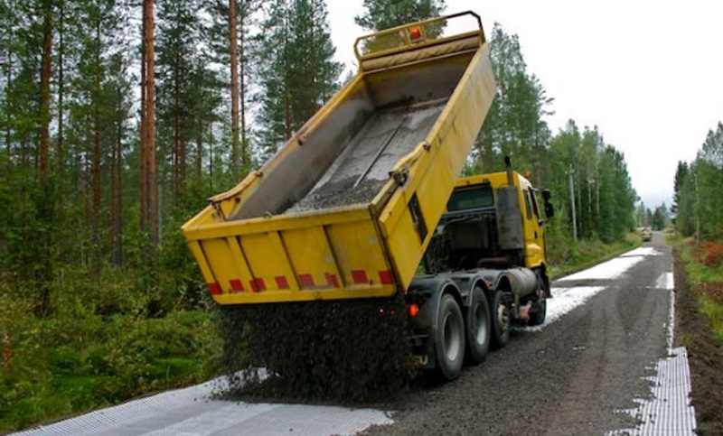
The geotextile is placed on the bottom of the excavation and 100 mm base course material is laid and compacted on it. The base course layer is shaped and compacted to the cross slope of 4% and the steel grid installed on it. The steel grid should extend into the inner slope by the length ‘A’, the steel grid’s installation depth. The steel grid should be installed so that the transversal steel wire will be the lowest. Normally 200 mm of base course material is laid over the steel grid. The base course is then shaped and compacted to the cross slope of 4% following which 100 mm of wearing course material is laid and compacted on top before being shaped to the cross slope of 4%. If old wearing course material is to be re-used, a proportion design should be carried out with the new wearing course containing a maximum of 50% of old material. Transition wedges should be constructed by shaping the base course material to the slope of 1:40 before laying the wearing course to the full thickness of 100 mm. A geotextile (filter cloth) is not normally used in transition structures.
3. Raising the road alignment, RA
If the new grade line will be raised any more than 50 cm, the solution is discussed as a raised road alignment or raising the grade line. A raised road alignment is often a relatively expensive solution for gravel and forest roads, so there normally needs to be additional considerations and benefits when this solution is selected. One special case is with differential frost heave problems where the alternative option is soil replacement which could be even more expensive. Other cases are road sections with drainage or flooding problems. The higher road alignment and increased bearing capacity would help to keep road open during flood. In forest roads small depressions with poor bearing capacity can reduce the speed of timber trucks before they start climb a steep gradient. On public gravel roads raised alignments also improve road safety due to better visibility.
RA working method description:
Removal of Old Material, Homogenization
Renovation is started with the removal of the existing wearing course material to the depth of 100 – 150 mm from the road surface. Old wearing course material should also be removed from the length of transition wedges. Wearing course material with high fines content should not be left under the new structure but it can be used later for the new wearing course material or on the road shoulders. After removing the old wearing course, the top 300 mm of the structure should be homogenized if needed. The homogenization is done in order to remove boulders and stones and create a homogenous platform for the new structures. Before placing the geotextile (filter cloth) the road should be shaped to the cross slope of 4 % and compacted.
New Layers
The geotextile is placed transversal to the road direction overlapping at least 500 mm. The thickness of 200 – 300 mm or > 300 mm of subbase material and the thickness of 200 mm base course material are compacted on the geotextile. The constructed layers are shaped and compacted to the cross slope of 4 % and 100 mm wearing course material is laid on them. Also the wearing course is shaped to the cross slope of 4 %. If old wearing course material is to be re-used, a proportion design should be carried out with the new wearing course containing a maximum of 50% of old material. The transition wedges are constructed by shaping the base course material to the slope of 1:40, the wearing course is constructed to the full thickness of 100 mm. The geotextile (filter cloth) is not normally used in the transition structures.
4. Soil replacement, SRP
Soil replacement is normally used when the road alignment cannot be raised sufficiently to build a high enough bearing capacity, or the subgrade soil is frost susceptible and the road is suffering from severe frost damage such as differential frost heave bumps. The soil replacement depth on gravel roads is normally 600 – 1200 mm. A typical location for a soil replacement structure is where differential frost heave problems or spring thaw weakening are located on the top of a hill. Special soil replacement has been used on roads where the bedrock surface is close to the road structure and the road has frost or other problems.
SRP working method description:
Removal of Old Material, Filter Cloth Installation and Transition Wedges 1:15
Rehabilitation is started with the removal of the existing material to the depth of 100 – 150 mm from the road surface. Old wearing course material should also be removed from the length of transition wedges. Wearing course material with high fines content should not be left under the new structure but it can be used later for the new wearing course material or on the road shoulders. After removing the old wearing course, the old material is excavated to the depth of 600 – 900 mm (shallow replacement), or >900 mm (deep replacement) from the road surface. The geotextile (filter cloth) is placed on the bottom of the excavation. The width of the excavation can be determined by using the figure below. A part of the old material can be used on the road shoulders if needed.
9.3.6. Special considerations in design and execution
In addition to the general renovation design guidelines above there are also a few special considerations needed to be aware of.
Spring thaw weakening sections
An exact renovation design of sections with spring thaw weakening damages is more challenging than normal sections with bearing capacity problems because deflection surveys carried out in spring with frost in the subgrade normally give results that are too good. Similarly FWD surveys made in the dry summer months can also give results that are too good. That is why renovation design for spring thaw weakening damage sections is normally based on the type of spring thaw weakening, and on the evaluation of the severity level of the damages. For example, if spring thaw weakening problems are severe the maximum deflections and surface moduli during the summer can be two times higher than during the worst days in spring. In this case the strengthening Basic Structure (BS) solution could be Option 3, 300 mm base course and 100 mm wearing course. If spring thaw damages are not so severe, then the BS could be Option 2, 200 mm base course and 100 mm wearing course.
The other thing that should be remembered in the design is that because drainage is always improved during spring thaw weakening cases, the actual bearing capacity after the rehabilitation will normally be slightly better compared to the design calculations. This benefit can however be lost over the medium term if the drainage is allowed to get worse again.
Finally, when designing renovation for spring thaw weakening sections, a very good and cheap option is cutting back any trees on the sunny side of the road if they are causing shady conditions on the road.
Differential frost heave sections
Road sections with differential frost heave problems are normally expensive to renovate properly. That is why in many cases the first thing to do is to try to improve the drainage system around the frost bump and thereby improve the bearing capacity over the section. Also in low lying areas raising the alignment might be a good solution. The extra aggregate load can act as an opposing force against frost heave and possibly slightly decrease the amount of frost heave. Together with drainage improvement this could be a sufficient solution as many times frost bumps are related to clogged access road culverts etc.
If the frost bump happens at a change from a road cut with a frost susceptible subgrade soil to a road embankment, a drainage improvement will most likely not work. In this case a transition wedge structure should be designed to even out the differential frost heave over a wider area. Transition wedge structures should also be used in the case of differential frost related to main road culverts.
Homogenization, removing boulders, stone crushing
If the gravel or forest road has been suffering from severe Mode 2 rutting problems or shoulder deformation and/or if it is likely that in the future frost action will push large number of big boulders to the road surface, it is recommended to design homogenization and boulder removal to the road. In addition homogenization machinery could be used as mixmilling to improve the grading of the old road material. In this case coarse grained base course aggregate or ballast is spread on the road surface and the mixed with the old material.
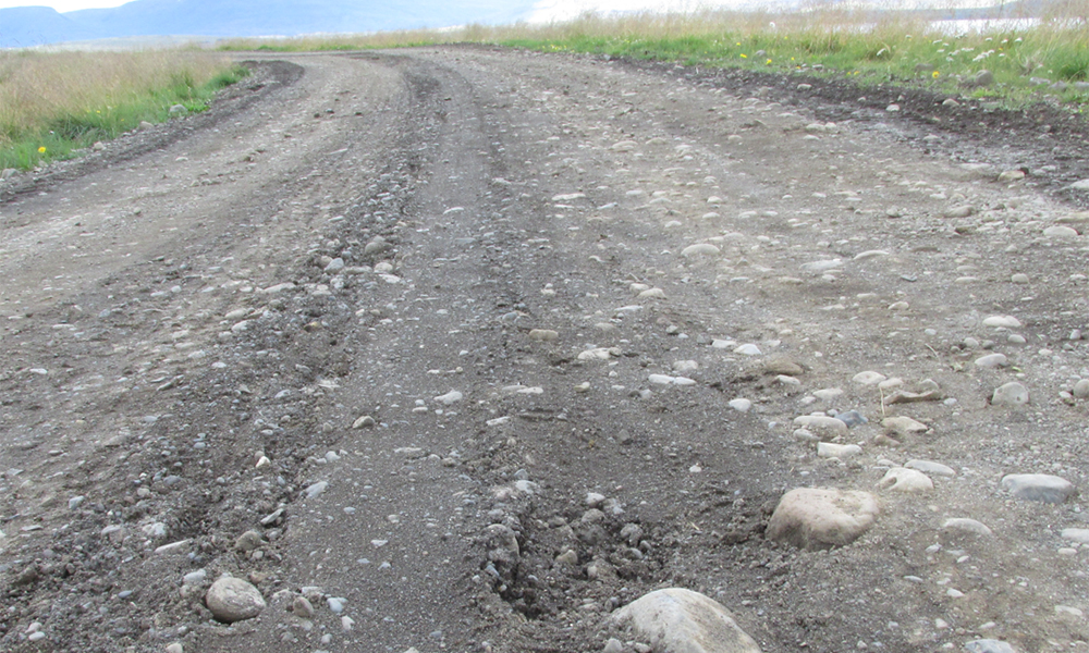
A special case in gravel road renovation is an old road where the base course has been made of natural gravel containing large stones. These stones will move under wheel load and will prevent the wearing course from performing properly. Stones can also cause windshield damages. If this is the case the recommended solution is to crush the stones.
Width control
The ROADEX project has been following the performance of renovated gravel roads in Finland and Sweden and the results show one very common factor on structures that failed. This was where road strengthening had been made across the whole width of a widened road, and the road had not been narrowed to the design width before the renovation. This regularly led to failures of the road shoulders after only 1-2 years after the renovation.
9.4 Renovation quality control / follow up
As in any road maintenance, paving or renovation projects, quality assurance and quality control are key parts of the project. In this work it should be ensured that the renovation works have been carried out according to the design and procurement documents, and that structures have been built on the right locations with the correct material quality according to the specifications. In addition it should be verified that the various layer thicknesses are in accordance with the design documents and that materials have been compacted properly. Even though digitalization is beginning to enter gravel or forest road construction projects, normally there have not yet been sufficient machine control systems in use, and as a result contractors use their own systems. For this reason quality control surveys are vital.
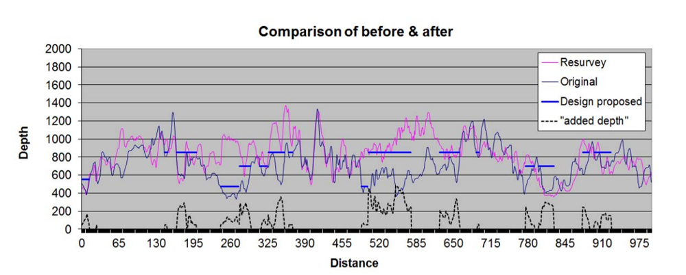
In quality control the design thicknesses vs constructed thicknesses can be checked point by point by drill cores or excavation pits, but the most efficient and reliable method is the GPR technique. GPR gives continuous thickness profiles for the layers that can be compared with the specified design thickness. ROADEX experiences so far have shown that construction thickness can sometimes vary from the design thickness, but generally the material amounts/volumes match the design.
The ROADEX project has also been carrying out FWD surveys on forest roads after the renovation and these results have shown that in most cases the measured bearing capacity is better that the design capacity. The main reason for this is most likely that the associated drainage improvement that has been carried out has dried out the materials in the road and subgrade soil, and due to improved stiffness the final bearing capacity is better. A further reason could be that the aggregate quality (moduli values) has been better than used in the design.
It is recommended that the renovated road is documented by taking photographs or video and measuring the road with a laser scanner. This will help to record the section for any future follow-up.
9.5 Benefits of ROADEX renovation design methods
There are many benefits of using the ROADEX gravel and forest road renovation target design. First of all, thanks to having continuous data over the whole road, all of the resources can be focused exactly on the problem spots. The second benefit is that the design can be made to meet the specific target bearing capacity value and money will be not wasted in increasing the bearing capacity on sections where it is not needed. These two benefits bring about major savings in renovation budgets, as well as the improved environmental issues thanks to reduced CO2 emissions.
The Timmerleden forest road renovation project compared the ROADEX design method with designs made by three experienced consultants using mainly traditional methods and techniques. In this comparison the ROADEX design was the cheapest, while the other designs were 15%-50% more expensive both in money and environmental costs. In general, survey and design costs can be about 5-15% of the standard renovation budget.
Unfortunately there are not yet any life cycle cost (lcc) calculations of the performance of these structures. But it can be assumed that after life cycle cost analysis the ROADEX method would be seen to be even more competitive compared to the traditional methods. It may be that in some cases the ROADEX solution may result in a more expensive solution than the traditional method. Savings will however come in the longer term from the lower life cycle costs.


