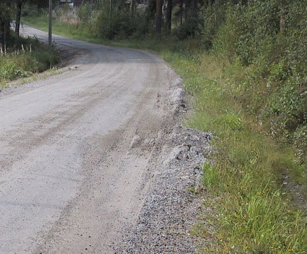
6.1 DRAINAGE MANAGEMENT
Results from the ROADEX project have shown that the lifetime of paved roads can be substantially increased by ensuring that the drainage system functions correctly.
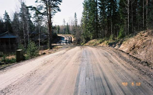
Good drainage management has also been proven to be the most cost-effective measure for dealing with permanent deformation, and/or problems with road condition management in general. For this reason, drainage should always be given the highest priority possible when selecting maintenance and rehabilitation measures. Results from the ROADEX project confirm that this general rule can be applied to all roads: paved, gravel and forest roads.
A standard drainage management process normally has five steps:
1. The collection of data on the drainage condition of the road network
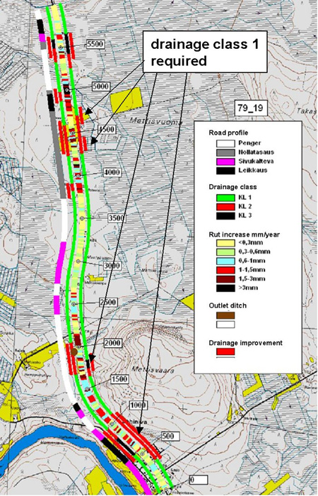
2. A drainage analysis to identify the critical sections requiring action
3. The preparation of a drainage rehabilitation, and/or maintenance plan, including definitions of the expected maintenance standards.
4. Details of the work required to improve the drainage condition in the critical sections up to the target level
5. Regular monitoring and maintenance actions to ensure that the drainage condition stays at a good level. This can be restricted initially to the identified critical sections and later everywhere in the road network.
6.2 MANAGING LOADING AND SEASONAL CHANGES
6.2.1 Truck weights and dimensions
Truck total weights have been a challenge for engineers working with asset management and pavement management issues as they can have a great impact on pavement fatigue and permanent deformations especially on low volume roads that are mainly designed to carry lower loads. In addition suspension systems of truck have an impact for the pavement performance.
Many times it has been stated that axle weights have not increased, only that the number of axles have increased to distribute the load. However latest research results from Finland have shown that increasing total weights has an impact on road performance and permanent deformation with roads built over weak subgrades.
On the other hand the movements towards higher total weights have been cutting down haulage costs resulting in a positive impact on the economics of rural areas. This increase in total weights will most likely continue in the near future as the CO2 emissions per haulage tonnes will be lower if heavier trucks are allowed to be used.
In addition to total weights the maximum lengths of trucks have been changing in some ROADEX partner countries. In Finland in 2019 34.5 m long trucks were allowed to be used in standard haulage. Their total weights are not allowed to increase from 76 tonnes. These trucks have a great impact in “lighter cargo” transports on main highways. For narrow low volume roads with poor geometry these long trucks do not fit well.
The table below presents a summary of weights and dimensions in Ireland, Scotland and Finland.
| Ireland | Scotland | Finland | |
|---|---|---|---|
| Max. allowed total weights | Rigid Truck 2 Axle: 18 t 3 Axle: 26 t 4 Axle: 32 t 5 Axle+: 36 tTractor unit and semi-trailer 3 Axle: 26 t 4 Axle: 38 t 5 Axle: 40 t 6 Axle: 46 t |
2 axles: 18 t 3 axles: 26 t 4 axles: 38 t 5 axles: 40 t 6 axles: 44 t |
4 axles: 36 t 5 axles: 44 t 6 axles: 53 t 7 axles: 60 t 8 axles: 64 t 8 axles, if at least 65 % of the trailer weight is on dual tyre axles: 68 t 9 axles: 69 t 9 axles, if at least 65 % of the trailer weight is on dual tyre axles: 76 t 10 axles: 74 t 11 axles or more: 76 t |
| Max. allowed steering axle weight | 10 t | 10 t | 10 t |
| Max. allowed driving axle weight | 9.5 t per axle if both axles are driving axles as part of a tandem 10.5 t for a sole driving axle 11.5 t (for a sole driving axle with Air suspension or an equivalent system) |
11,5 t | 11,5 t |
| Max. allowed triple bogie weight | 24 t with axle spacing 1.3m or greater | Tri-axles <1 m spacing: 21 t >1.3 m spacing: 24 t |
On truck, if at least two of the axles is equipped with dual tyres: 27 t On trailer: 24 t |
| HCT truck policy | No | No | Yes |
| Maximum allowed truck length | Truck & semi-trailer 16.5 m Rigid and drawbar combination 18.75m Large tractor drawing two trailers: 22m |
Truck + semi-trailer: 16.5 m Truck + trailer: 18.75 m |
Truck + semi-trailer: 23.00 m Truck + trailer: 34.50 m |
| Rules for tyre types | Yes | Yes | |
| Tyre pressure definitions | No | No | |
| Over load licensing | No | Yes |
A summary of weights and dimensions specifications in Ireland, Scotland and in Finland
Detailed information about weights and dimensions in Ireland can be found on Detailed Information about Weights and Dimensions in Ireland can be found on Guidelines on Maximum Weights and Dimensions of Mechanically Propelled Vehicles andTrailers, Including Manoeuvrability Criteria.
Sweden and Norway allow different heavy vehicle combinations to use their road network and also have bearing capacity (Bk) classifications on roads with special specifications based mainly on how heavy trucks can use different roads. In Norway the classification is made mainly on the maximum axle weight of free axle (10.8 and 6 tons). The distance of bogie axles also has an impact on the maximum loads.
| Ton | |||||
|---|---|---|---|---|---|
| Axle/axle combination | Axle distance (m) | Bk10 | BkT8 | Bk8 | Bk6 |
| Axle load (free axle) | 10 | 8 | 8 | 6 | |
| Axle load driving axle | 11.5 | 8 | 8 | 6 | |
| Load from two axles | 1.30–1.79 (bogie) | 18 | 14 | 12 | 9 |
| 1.20–1.29 (bogie) | 16 | 12 | 12 | 9 | |
| 0.8–1.19 | 15 | 11.5 | 11.5 | 8.5 | |
| Under 0.8 | 10 | 8 | 8 | 6 | |
| Triple bogie | 1.30–1.79 | 24 | 19 | 16 | 12 |
| 1.00–1.29 | 22 | 18 | 16 | 12 | |
| Under 1.00 | 16 | 12 | 12 | 9 | |
Highest allowed axle loads at roads with different bearing capacity (Bk) classes and based on bogie axle distance in Norway.
Sweden has the most complex Bk classification. Earlier there were 3 Bk classes but now a new Bk4 class has been defined for special transportation routes where total weights of maximum 74 tons are allowed. The maximum allowed total weight is mainly defined based on the distance between the first and last axle in the truck and trailer combination, defined as distance C in the figure below.
The following table provides examples of maximum allowed total weights in Sweden for two axle distances C (min and max).
| BK1 | BK2 | BK3 | BK4 | |
|---|---|---|---|---|
| Dist C | 10 m | 10 m | 10 m | 10 m |
| Max weight (10 m) | 50 t | 31 t | 22.5 t | 49 t |
| Max dist C | 20.2 m | 18.5 m | 22 m | 20.2 m |
| Max weight | 64 t | 54.4 t | 37 t | 74 t |
Highest allowed total weighs in Sweden in two distances between first and last axle: 10 m and maximum allowed distance.
The following table provides examples maximum allowed axle weights in Sweden:
| BK1 | BK2 | BK3 | BK4 | |
|---|---|---|---|---|
| 1. Single axle | ||||
| Free axle | 10 t | 10 t | 8 t | 10 t |
| Driving axle | 11.5 t | 10 t | 8 t | 11.5 t |
| 2. Bogie axle | ||||
| Distance < 1.0 m | 11.5 t | 11.5 t | 11.5 t | 11.5 t |
| Distance > 1.8 m | 20 t | 16 t | 12 t | 20 t |
| 3. Triple bogie | ||||
| Distance < 2.6 m | 21 t | 20 t | 13 t | 21 t |
| Distance > 4.7 m | 26 t | 22 t | 13 t | 26 t |
Highest allowed axle loads at roads with different bearing capacity (BK 1-4) classes and based on maximum axle distance (C) in Sweden.
Currently about 20% of the state roads in Sweden are classified as BK4 roads and more roads will have BK4 status in 2022-2025.
Detailed information about weights and dimensions in Sweden can be found on https://www.transportstyrelsen.se/sv/publikationer-och-rapporter/Publikationer/Vag/Yrkestrafik/Lasta-lagligt1/Legal-loading/.
6.2.2 Permanent load restrictions
Permanent load restrictions are normally used on a road when it is considered that the road will not have sufficient construction to carry the expected heavy traffic other than when it is frozen during winter.
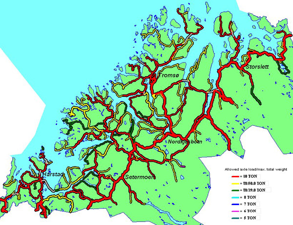
Within the ROADEX partner areas, permanent restrictions are commonly used in Norway but they are also used to some extent in Sweden and in Scotland. “Road Condition Management of Low Traffic Roads in the Northern Periphery”
Permanent restrictions can also be used where there are weak bridges. More information about permanent load restrictions can be found in the ROADEX I report “Road Condition Management of Low Traffic Roads in the Northern Periphery”.
The aim of permanent restrictions is to reduce imposed stresses on road structures, and the risk of permanent deformations. This protects the road, but has the downside of creating obstacles to the economic development of communities served by the road.
6.2.3 Temporary load restrictions
Temporary weight restrictions are used in most areas where the road structure is frozen for at least part of the year. During the critical seasons, when the bearing capacity of the road is at its weakest, many weak low volume roads need protection. Examples of this can be found in Scandinavia, Russia, northern China, Canada and the northern U.S.A. Scotland also uses temporary weight restrictions. Norway is an exception to this general practice. Temporary weight restrictions have not been permitted there since 1995 and only permanent weight restrictions are used on weak roads.
Heavy transportation industries are now important economic drivers for rural areas, particularly those of the forestry and fishing industries, and as a result roads organisations are coming under increasing pressures to lower the number, and duration, of their temporary weight restrictions. Recently the USA and Canada have started permitting higher axle loads in winter using winter premiums.
When road organisations are considering applying restrictions the questions normally asked are: a) What are the roads / road sections that should be restricted? b) Is there a need for a temporary load restriction every year? c) When it should be applied? d) What is the maximum axle load or total weight that should be imposed? e) When can the load restrictions be removed? and f) How will the loads be monitored during the restrictions? Each country has their own policy and these systems are described in detail in ROADEX reports on Spring Thaw Weakening. The following brief answers can however be given to these questions.
What are the roads / road sections that should be restricted?
Normally the decision on which roads, or road sections, need load restrictions is made based on old experience of the roads, i.e. the roads that have suffered from severe spring thaw weakening problems in previous years. This can be ascertained from the spring thaw weakening data base, if such exists. A good example of this is from Finland where the decision on restrictions is normally made based on the severity and repeatability of previous spring thaw problems. Another way to determine the need for load restrictions is through a risk analysis that has been tested in the ROADEX project. This analysis identifies where the problems are expected and how severe they will be if restrictions are not applied. The analyses are usually made based on GPR data, FWD data and drainage condition. Data from profilometer surveys can also be useful in risk analyses of paved roads if it is available.
Are load restrictions needed annually?
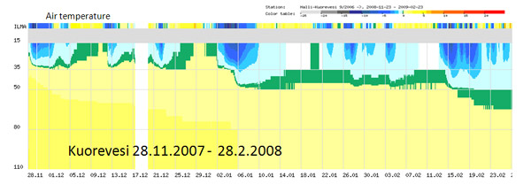
Some of the weakest roads will need load restrictions every year but most roads will only have problems during the most severe winter freeze-thaw cycle periods, or during spring thaw weakening periods. The need for load restrictions can be determined from historical data, if it exists, but some risk predictions can also be made. The risk of a severe spring thaw weakening can be evaluated in the early winter after the roads have been frozen.
The risk for severe spring thaw problems will be high if the roads were wet when they froze, and groundwater tables were high. Conversely, mild spring thaw problems can be predicted if the roads were dry when they were frozen. A similar prediction can also be made if the air temperatures were very low during the early freezing period and the frost line penetrated quickly to the subgrade without forming ice lenses. However, it should always be kept in mind that the weather, and the amount of heavy traffic, during the thawing period will have the greatest impact on whether a road will have spring thaw weakening problems and the need for load restrictions.
When should load restrictions be applied?
The ROADEX surveys have revealed that the most critical time to successfully overcome spring thaw is during the early spring when the road surfaces start to thaw. If the weather is dry at this time, and the roads are not loaded too frequently, with long enough recovery times between loadings, there is a good chance that any water will evaporate quickly from the surface layers and that a ”dry crust” will form on top of the structures. When there is a confident prediction of spring thaw problems, and roads are expected to have heavy traffic, restrictions should be applied as soon as the frost front has thawed to the level of 100 – 150 mm below the road surface. It is extremely important to monitor the moisture content of the road and weather conditions at this time.
What is the maximum allowed axle load / total weight allowed?
This is a very difficult question and the ROADEX project could not give any simple answers to it. One way that has been used in some areas is to use FWD summer deflection data as a reference source to fix acceptable deflections, and during the spring thaw period to test the road with different load levels. A restriction could then be placed on those loads that exceeded 2 times the summer reference deflection.
When can load restrictions be removed?
Weight restrictions can, and should, be removed immediately there is strong enough evidence that the road can carry heavy vehicle loads.
This can be done based on data from a spring thaw weakening monitoring station, or from FWD or lightweight FWD
or DCP (12)surveys, by making test loadings, or just based on visual evaluations made by the local road engineer. ROADEX reports have detailed descriptions on how to use these techniques.
How loads are monitored during the restriction time?
There are no special systems for monitoring loads during the spring thaw weakening. Monitoring policies for axle loads and total weights vary greatly from country to country across Northern Periphery as the figure shows.
| Ireland | Scotland | Iceland | Norway | Sweden | Finland | |
|---|---|---|---|---|---|---|
| Control enforcing authority | Police | Police | Police | Road Region / Traffic dept. | Police on assignment from road authority | Police |
| Primary object of control | Weight and axle spread. Width and length | Vehicle length and width, plated vehicle weight | Axle load and total weight | Axle load, wheel load | Axle load | Axle load |
| Control equipment | Weighbridge transportable scales | Weighbridge transportable scales | Stationary / portable scales | Stationary / portable scales | Stationary / portable scales | Portable scales |
| Sanctions | Progressive monetary fines for both vehicle owner and driver, penalty points driving licence | Penalty fees, unloading, revocation of operator license | Stepped progressive penalty fees | Penalty fees, unloading, revocation of license | Progressive penalty fees (both driver and haulage co.) | Stepped progressive penalties |
Table summarising the load restriction policies of some countries in the ROADEX partner countries.
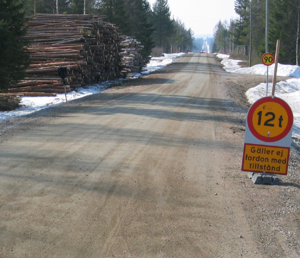
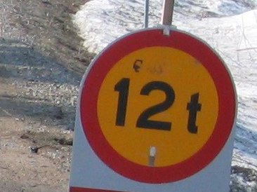
The easiest, and most commonly, used way to monitor loads during temporary load restrictions is to apply a 12 tonnes maximum total weight on the road. This effectively means that only unloaded trucks can drive on the road. If empty trucks need to be prohibited the maximum weight should be restricted to 6 tonnes. In Scotland vehicles can also be restricted by defining a maximum allowed length for the vehicle.
6.2.4 Recovery time
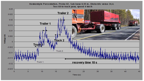
One option for load restrictions in the future could be the use of road recovery times to protect roads from major failures during the spring thaw. As the ROADEX project results have clearly showed, road materials and subgrade soils that do not have an entirely elastic behaviour need time to recover from a heavy vehicle passing.
video=”https://www.roadex.org/wp-content/uploads/elearning/flash/videos/623_1.mp4″ /]
This recovery can be roughly divided into two parts a) the recovery of the structural orientation of tightly and loosely bound water molecules in the base course and their rearrangement,
and b) the recovery of the pumping effect. The first of these, the recovery and rearrangement of the pore water molecules can have an effect on Mode 1 rutting on roads with relatively high traffic volumes, but the underlying physical/chemical process is not yet clear.
The second part, pumping, is very important for low volume roads with weak subgrade such as silts and peat when the upper road structures are not stiff enough to spread the load to a wider area. In this pumping recovery phase, the worst thing that can happen to the road is convoy driving with several heavy trucks driving close to each other.
This leads to a fast and severe failure of the road.
However, when it is known that the road is sensitive to permanent deformation, the information can be used for road condition management during spring thaw periods, or during winter freeze-thaw cycles.
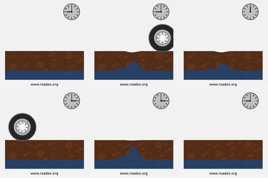
A good example of this local practical experience comes from Sweden where a local maintenance contractor gave “time slots” to heavy trucks that wanted to use the road. Based on the strength of the road structures these slots were given either in 6 or 8 hours intervals.
The recovery time of a particular road section is dependent on the road structure and on the severity of the spring thaw period. Detailed information on recovery times is not yet available and further research is needed. But based on the interviews during the ROADEX project some general conclusions can be reached. On weak paved roads recovery times can be 3-4 hours, on stronger gravel roads 6 hours, on weaker gravel roads 8-10 hours, and on stronger forest roads 10-12 hours. On weaker forest roads heavy traffic should not be allowed to use the road or, if the use is necessary, the recovery time should be specified to be at least one day.
The ROADEX results have also shown that long loading times increase the time the road needs to recover. Drivers should therefore be advised to drive these roads relatively quickly and not to stop on the weakest places.
One option to allow heavy transports during the spring thaw weakening time is to allow them in early spring during the night times when the roads are frozen.
6.2.5 CTI
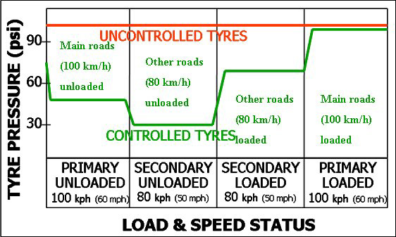
An alternative way of reducing the stresses on a road is to amend the contact pressure of vehicle’s tyres on the road by reducing the pressure in the tyres. “Central Tyre Inflation” (CTI), is the generally accepted terminology for the onboard automated system of tyre pressure control that permits the driver of a vehicle to adjust the pressure of the tyres on the vehicle whilst the vehicle is in motion. A number of automated systems are available worldwide. Tyre Pressure Control on Timber Haulage Vehicles.
Tyre manufacturers recommend that tyres should be inflated to suit the load on the tyre, the speed of the vehicle and the type of use. Their recommended pressures are a ”best fit“ to suit the overall daily work of the vehicle, and do not produce the best contact area at all times. CTI makes it possible to suit the changing circumstances encountered by the vehicle during its working day: loaded or unloaded, slow or fast vehicle speed, type and bearing capacity of the road, road surface properties, and others.
In its simplest form CTI takes compressed air from the vehicle’s onboard compressor and routes it through air hoses, under control, to inflate the vehicle’s tyres. The radial tyres that are fitted to heavy vehicles do not change their width with pressure change and as result, lowering (or raising) the pressure in a radial tyre, increases (or reduces) the tyre’s contact length, or “footprint”, on the road surface. This action lowers the stress level on road especially close to the road surface.
CTI is very good for minimising Mode 1 rutting.

It also allows the surface of the road to cure faster and increase its stiffness quicker.
A further benefit of CTI is that it equalises tyre pressures in twin tyred systems giving rise to better distribution of load between the tyres and equal contact patterns on the roads.
CTI systems are stated to offer also other benefits. It is claimed that they improve vehicle responses at speed on main roads through having optimum tyre/road contact. Off road, flexible tyres and longer footprints give greater flexibility and improved traction on rough and weak forest roads. This helps to reduce tyre slip and enables vehicles to negotiate loose, undulating, stony surfaces with minimum tyre damage. Low pressure tyres are also said to better deal with bumps and rough surfaces, minimising vibration into the truck and driver.
6.2.6 Axle configurations and tyre wander
Mode 1 rutting problems on forest roads can be managed, or reduced, by using vehicles with special axle configurations or by driving in varying lateral position of the road cross section. An example of first option can be seen in Scotland, where the tyres of a truck have been specially constructed to be out of line longitudinally, and thus act as roller compactor preventing the formation of ruts.
In these “Low Ground Pressure” trucks, the tyres are placed on different parts of the truck axles in order to minimise repeated load cycles on the road structure. The axles and wheels are designed to reduce the ground pressure overall and spread more of the weight of the vehicle over the middle of the road, where the road is at its strongest. This configuration evenly rolls and evens out the road surface, and reduces rutting. It is particularly useful in Scotland where super single tyres are regularly used for timber haulage.
“Low ground pressure” systems have been successfully used in forest roads in Scotland for a number of years and the experiences have been extremely good. The main problem with the vehicles is that they are only permitted to travel on forest roads because they tend to tear the pavement, or wearing course, on sharp curves. For this reason, they are only used at present for the transport of timber over weak forest road sections to temporary stockpiles close to paved roads.
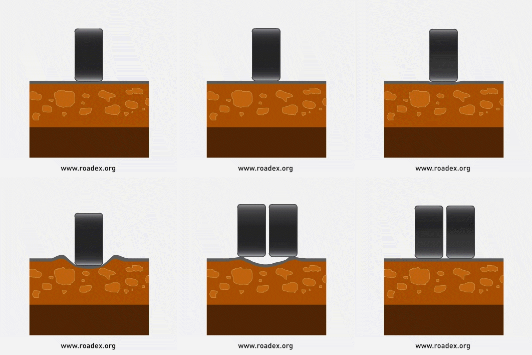
Another option to manage permanent deformation is “artificial tyre wander” which means that loaded trucks are driving in different part of road cross section which causes a specific rebound effect for the permanent deformation and thus reduces rutting. This phenomenon has been found in Finland when testing HCT trucks with increasing number of axles driving exactly on the same sport. The same potential problem will be faced also if and when autonomous trucks will be allowed to drive on exactly the same lateral location. This problem can be, and has been, prevented by heavy trucks driving on different locations on road cross sections always when possible.
Demonstration of an effect of a rut depth rebound effect of a truck driving first at one lateral position and later another position and later 0.6 m away from the first survey line.
6.3 MANAGING FUNCTIONAL CONDITION
The management of the functional condition of a road network is normally set out in the descriptions of the works, duties and tasks of the maintenance contract document. Of these, drainage maintenance is, by far, the most important factor for managing permanent deformation issues and, because of this, the ROADEX Partners commissioned a special “Drainage” eLearning lesson. Additional to this, there are some other small, but important steps that the contractor can take to improve the functional condition of a road, and reduce permanent deformation problems.
One issue that can save a road, when properly done, is the timely removal of snow from the road shoulder during the spring. This technique prevents the melting water from infiltrating the road structures at a time when the bearing capacity is at its most critical.
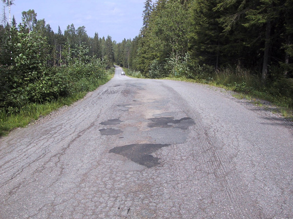
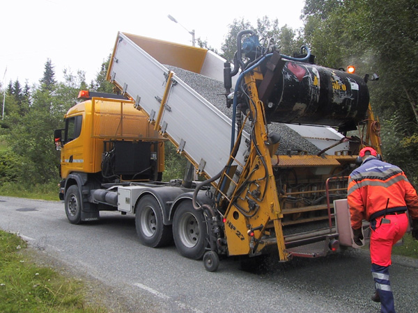
Another way of reducing permanent deformation problems is to keep the road surface as smooth as possible. Uneven road surfaces can cause undulating dynamic loads to the road structure and accelerate failures. This means setting up an effective pothole repair and patching service on paved roads,
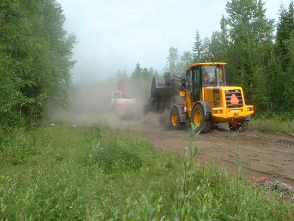
and using graders more frequently on gravel roads. Better functional condition on a road network will bring better feedback from road users, and more satisfied and healthier truck drivers.
And a final operation that can be employed is surface dressing. This is mainly carried out by specialist contractors and is recommended by ROADEX. Surface dressing provides a good seal to a road pavement, that prevents water infiltration into the road structure, and thus reduces permanent deformation problems.
6.4 MANAGING STRUCTURAL CONDITION
6.4.1 General – structural options
If a road is already exhibiting permanent deformation problems, such as deep ruts, improving the drainage alone will not be totally effective. Any structures that have been already damaged will also need to be repaired. A number of factors will therefore need to be considered on how best to improve and manage the road structures in a section of road before a final decision will be able to be made on an overall management strategy. These are:
Assignment
The ‘assignment’ is the most important issue to clarify at the outset of a project as it provides the framework for the rest of the project. In particular it should be established if the work is to be a temporary solution (6-10 years) or whether it is planned to last longer (20 years). For this reason, the following topics should be raised when discussing the assignment for a project:
- the resources available (money for the project, in-house project, external contractors, sub-contractors)
- the timetables, the special times of the year when construction is not permitted
- accessibility by heavy traffic, is it 24h / 365days?
- the lifetime required, guarantees, follow up parameters
- the basic design parameters for dimensioning the structures; elastic response, permanent deformation, frost heave
- the geometry of the road, can it be improved?
- the width of the road
- traffic management during the work, are road closures allowed?
Initial road data, problem diagnosis
This group is another critical element for a successful and sustainable project. These parameters define the cost of the project and are the major source for any savings in the project. Some factors will be more or less fixed prices. Items that should be considered at this point are:
- Road condition performance history
- road analysis and problem diagnosis data
- pavement thickness and its quality
- base course thickness and quality
- other road structures, thickness and quality
- subgrade soil; quality, stiffness, frost susceptibility, compressibility
- drainage condition
- topography
- seasonal changes, spring thaw weakening problems
- winter maintenance problems
- weak bridges
Aggregates available
If there are local good quality road aggregates available, and the price is reasonable, they should always be the first choice when selecting structural options. Suitable aggregates include:
- crushed materials, their quality and price
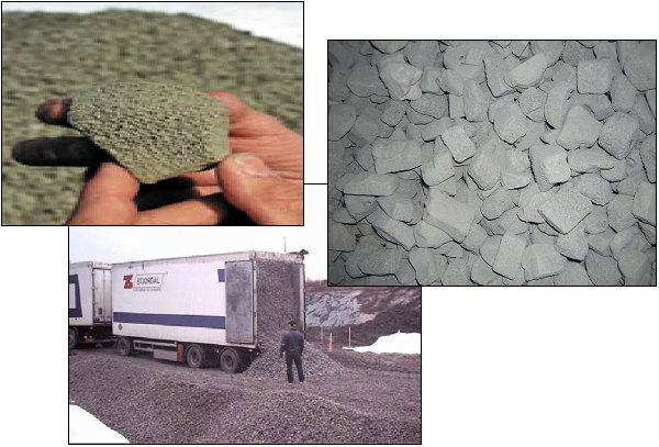
- slag or any other industrial byproducts available and their price
- non-frost susceptible aggregates available and their price (gravel, sand, etc)
Treatment materials available, and other special road construction materials
The availability and the price of treatment materials and other road construction materials should be identified at this time. The prices offered at this (design) stage will usually be fixed list prices for countries and areas, especially for traditional binders (bitumen, cement). Possible considerations here are:
- new treatment materials available
- geotextiles available and their price
- steel grids and geogrids available and their price
- insulation materials available and their price
Equipment available for the project
This is an important issue. It is not sensible to try to design a structure that requires equipment that is not locally available, or is too heavy to be transported to the site. Types of equipment that should be checked for availability and weight are:
- milling machinery, mixers
- compaction units
- graders
- stabilization units
- pavement remix units
- local asphalt plants
- quarrying machinery, and the unit price for quarrying and bedrock blasting
Environmental issues
Environmental issues should be always kept in mind when considering structural rehabilitation and management options. Environmental issues are discussed in detail in the ROADEX “Environmental Considerations” eLearning package and in other ROADEX publications. The matters listed in the following checklist should be assessed in every project:
- local natural protection areas
- ground water protection areas
- local special plant, animal or fish habitat
- possible noise problems
- possible vibration problems
- possible dust problems
- treatment agents and their risk to the environment
Other special local issues
A number of ”special” issues also need to be considered during the design phase to avoid unpleasant surprises later on site. An example of this is the identification of areas for materials excavated in improving drainage and/or excavated from soil replacement sites. The unit prices / taxes for dumping of excavated material should also be ascertained. These considerations vary from country to country.
The following “examples” provide some general information on typical structural options that can be used to improve structural conditions on rural roads.
6.4.2 New layers on the top
Adding new layers on top of the existing layers is the “classic” solution to permanent deformation problems as it effectively reduces the strains causing Mode 2 rutting and decreases frost problems. The method works well if the structure is well designed and there is new material locally available for the structures. However, it has been widely used as a “patent medicine” for all problems without thought for the underlying reasons for the problems, and many structures have failed soon after construction as a result of this.

Adding new layers should be used as a solution particularly when:
- the road is suffering from Mode 2 rutting problems. (It can also help with Mode 1 rutting and pumping problems)
- drainage cannot be effectively improved, or would be expensive
- the road has frost heave problems
There are however a few things that should be kept in mind when considering the addition of new layers:
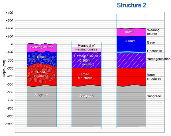
- If the rutting mode is Mode 1, and the old poor-quality structure is to be left in the road, the combined new layer thickness should be at least 150 mm (minimum). ROADEX II research results have shown that this is the most critical depth for permanent deformation. For this reason, it is recommended that the minimum thickness should generally be 200 mm, and on a gravel road with spring thaw weakening problems the thickness should be 300 mm (including the new wearing course).
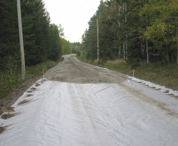
- Use a geofabric/geotextile if there is a risk that the old structures or subgrade could mix with the new structure, or if there is a risk of pumping.
- Do not leave old impermeable pavement beneath the structure, i.e. do not make a “sandwich structure”. If old pavement must be left, the thickness of the new unbound layers should be at least 40 cm.
- Do not leave old wearing course beneath the structure in a gravel road. It is frost susceptible and is sensitive to permanent deformation. It can however be used as source material for new wearing course.
- If the subgrade has large boulders close to surface remove them before adding any new layers. This will make the foundation more homogenous. But do not do this in the late fall when road structures are likely to be wet.
- If the road has pumping problems, consider using a very coarse-grained layer in the base course.
Other benefits of the structure:
- Reduced winter maintenance costs
- Reduced risk for flooding and erosion problems
- Reduced frost heave related problems due to increased load
New layers on the top might not be the best option if:
- There is insufficient road width. Keep in mind that raising the grade line requires more space for the road – or steeper inner slopes. Guard rails may be necessary.
- The road is located in an urban area (village) with house exit roads, drainage wells, pipelines etc.
- The road has guard rails. These will have to be lifted.
- The problem is located on the top part of a hill (traffic safety is reduced).
- The road is located on a compressible peat, gyttja or clay subgrade.
Finally, new bound layer on the top should considered if:
New asphalt or soft bitumen asphalt overlay can most cost effective solution in the following cases:
- The measured pavement strains start to be close to alarm value and rut increase rate has been growing but the pavement has not any visual distresses. In this case the lifecycle cost of the new pavement can be 60% lower compared to if asphalt has got visual cracks and has lost its tensile strength.
- Statistical analysis has shown a clear correlation between pavement thickness and rut increase rate and road has thin pavement.
- On rehabilitation projects to those sections that are relatively ok, have pavement thinner than 100-150 mm and have rutting values > 100 mm. This ensures that there will not be needed any measures over the next 10-20 years.
6.4.3 Mixmilling
‘Mixmilling’ is a technique where the pavement and base course are mixed together using a mixmilling machine. After mixing the road structure is normally shaped and compacted, and new pavement is laid on the top of the mixmilled structure. In this way the grading of the mixed base course will have been improved as material from the old pavement will have been mixed into it. This also makes the base course a little stiffer.
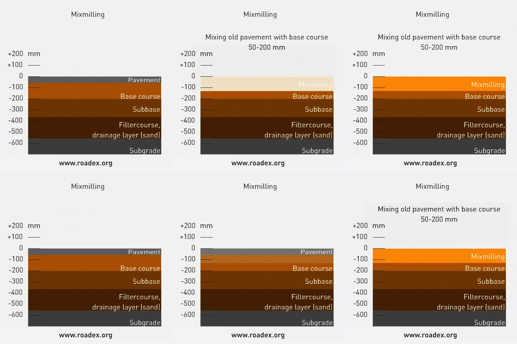
Mixmilling is an ideal technique where a road has major rutting problems, has lost its shape, and its crossfall is poor. When properly carried out, the top part of the road will become homogenous and a good crossfall can be restored.
The technique is however only marginally beneficial in improving bearing capacity problems. Any improvement in stiffness will be based only on a slightly better base course of mixed old bituminous layers and the new pavement layer on the top. For this reason, drainage improvement should be always done in association with mixmilling, or one year before. In this way the lifetime of these structures can be markedly improved.
Mixmilling is one of the cheapest solutions available to improve a paved road with severe rutting problems. It should/could be tried, together with drainage improvement, as a first rehabilitation solution on low volume roads before any other measure.
6.4.4 Mixmilling + new aggregate, coarsening
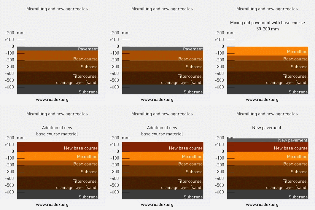
Mixmilling can also be carried out by adding new base course aggregates where the grading of the existing base course is poor. In this case the new aggregate is laid on the top of the old pavement before mixing the structure. The technique can be similarly used in gravel roads where it is called “coarsening”.

Mixmilling with new aggregate can also be carried out by first mixmilling the old pavement and base together before adding the new aggregate. The road can then be shaped with a grader as before and the structure mixmilled again.

Mixmilling can be used in raising the grade line for roads with frost heave and/or Mode 2 rutting problems, and poor crossfall. In this case the old structure is first mixmilled, shaped and compacted. The new base course aggregate is then laid on top and, if necessary, partly mixmilled with the lower structure. Finally, a new pavement is laid on the compacted mixed layers. This structure is effective in increasing the bearing capacity of a road and it can also reduce frost problems.
6.4.4.1 Mixmilling and crushing
A new method is gaining in popularity in Finland especially for the improvement of public gravel roads and forest roads. The “Tirkkonen method” combines deep mixmilling with the crushing of large stones into the road structure thereby improving the grading of the combined material. It is especially effective in areas with boulders and big stones in the road structure and subgrade soil that are causing problems for the performance of the road. The method also has the benefit that it can mixmill to a depth of up to 50 cm.
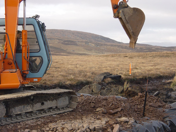
The work is normally started by removing the largest boulders from the road and subgrade with an excavator. This is normally done to a depth of 0,8 – 1,0 m. The excavated boulders, normally larger than 200 mm, are placed to the side of the road for re-use, e.g. to be transported and crushed in a local crushing plant, or used in erosion protection, or for increasing slope stability.
After the boulders have been removed the road structures can be mixed and at the same time any remaining large stones in the road structure can be crushed using proprietary tractor driven machinery.
After the mixing/crushing has been carried out the road structure is compacted and shaped and a new wearing course placed on top.
6.4.5 Treatment or stabilisation
Treatment, or stabilisation, of the base course can be a particularly effective solution for roads with Mode 1 rutting problems and minor differential frost heave (both longitudinal and transverse). “Treatment” of the base course material improves its resistance to permanent deformation. “Stabilisation”, on the other hand, stiffens the base course material to such an extent that it is possible to take a solid drill core from the layer. The major problem with base course materials in the Northern Periphery is not however their low resilient modulus but their resistance against permanent deformation. ‘Treatment’ of base course layers should therefore be considered as a serious and cost-effective option for low volume road rehabilitation projects.
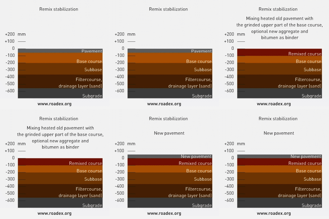
Treatment and stabilisation techniques are described more detailed in lesson 7.4.3.
Good laboratory tests are critical in every project to ensure good results. Any differential frost heave problems should be dealt with before starting the treatment or stabilisation of a base course.
New non-traditional treatment agents will be a very attractive option in the future for strengthening short sections of low volume roads and forest roads with permanent deformation problems, especially where good quality new aggregates are not available locally.
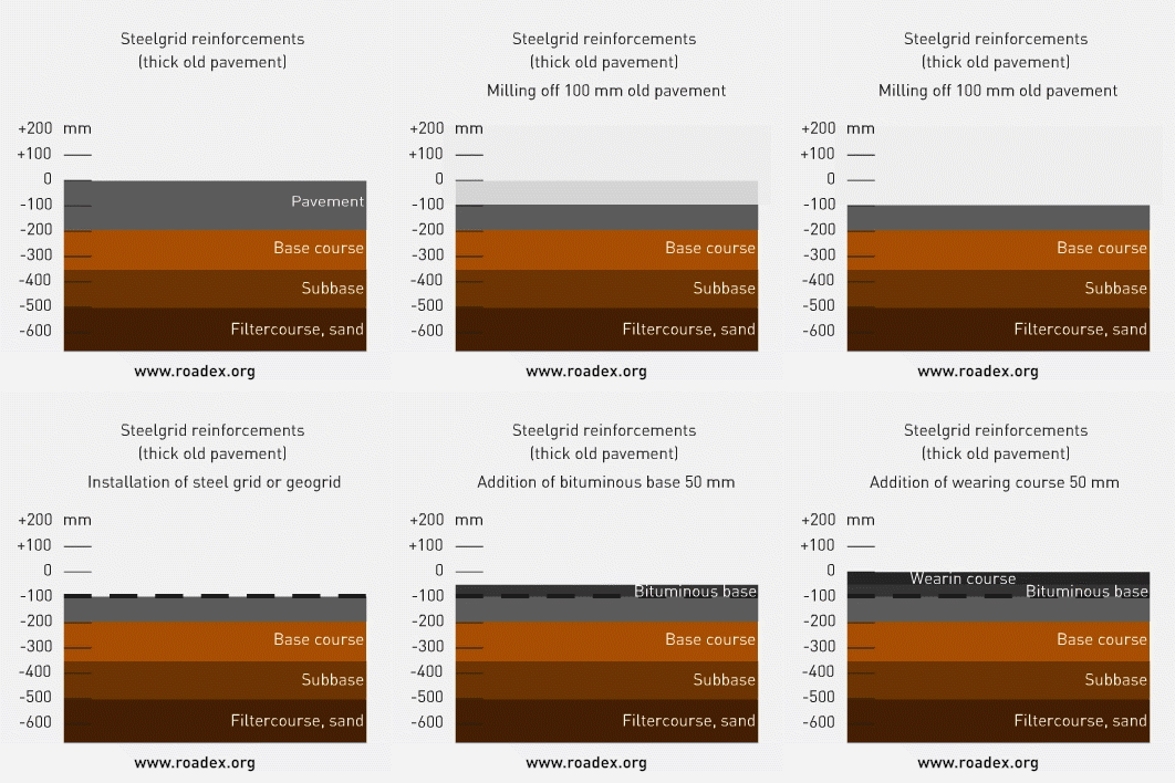
6.4.6 Steel grid / geogrid reinforcements
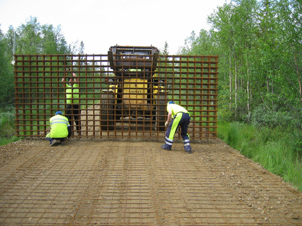
Steel grids have traditionally been used for longitudinal cracking problems against differential frost heave in the transverse direction.
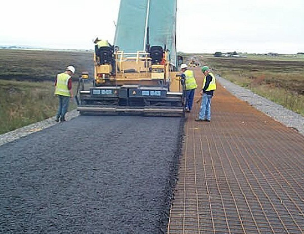
They can also however be used to strengthen roads with Mode 2 rutting problems, or pumping on soft subgrade soils. In these cases, the steel grid spreads the load across a wider area and reduces the vertical stress at the road structure-subgrade interface.
When designing a steel grid structure against permanent deformation the installation depth should be deep enough (20 – 25 cm from the surface) to ensure that a tensile effect is created under the load. The material surrounding the steel grid should be coarse enough to ensure that interlocking occurs between the aggregate and the steel grid. In those locations where the existing road has insufficient coarse aggregate ROADEX recommends that at least 5 cm of coarse base course material is laid under the steel grid.
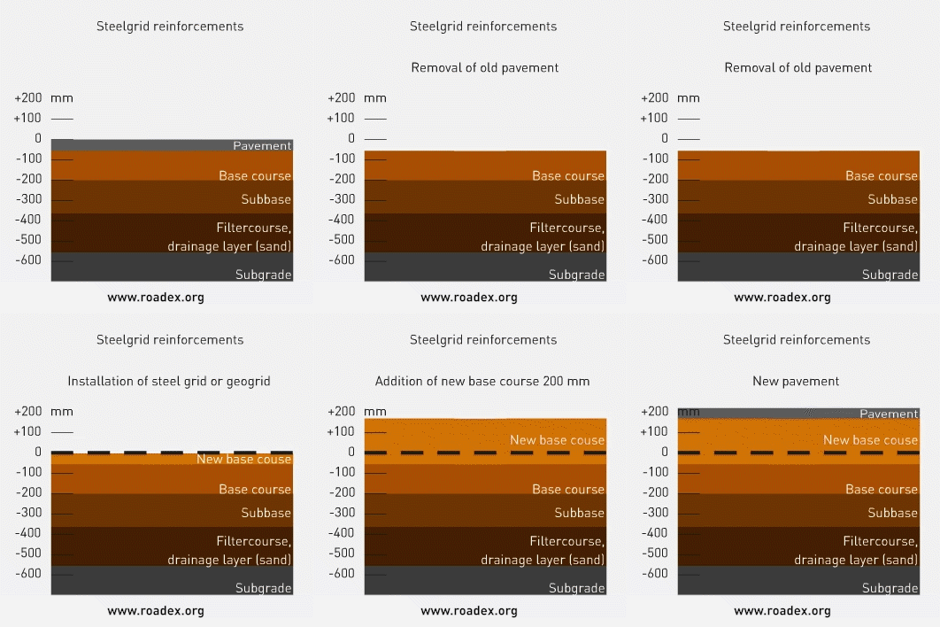
If the problem involves pumping within a road on a weak peat subgrade or grade line cannot be raised, a good solution is to remove some of the existing road construction layers first before installing the steel grid. This can prevent unwanted differential settlement later in the life of the road.

Geogrids can be also good solutions where a pavement is suffering from Mode 1 rutting. This type of structure has been successfully used in Scotland.
A steel grid can be installed into a bituminous pavement if it is thick enough. In this case the minimum installation depth should be 100 mm. Test results from ROADEX I showed that if the grid is installed higher in the road rutting problems may develop. ROADEX recommends that steel grids should be installed in unbound layers at depth of 200 – 250 mm.
6.4.7 Soil replacement
Soil replacement should be considered/used where a road is suffering from differential frost heave, as well as permanent deformation, and where there would be major problems in raising the grade line. The technique is particularly suitable for problems located within road cuts, or moraine hummocks.

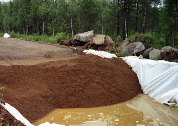
Soil replacement can also be used where the subgrade contains large boulders.
Shallow soil replacement with steel reinforcement can be used where the subgrade soil is compressible peat.
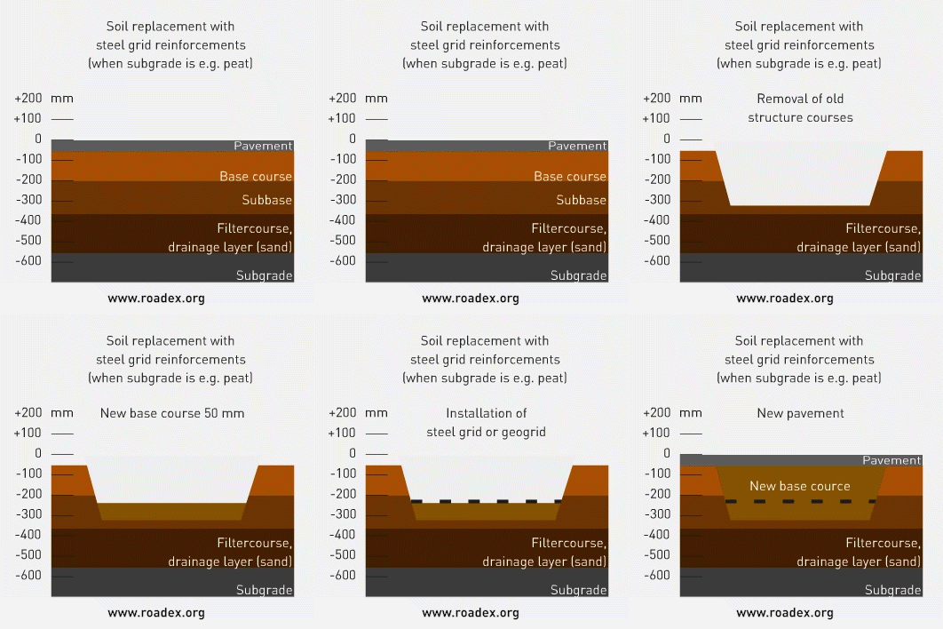
Transition wedge structures should be always used when making soil replacement structures.
Thick soil replacement is seldom an economical solution on low volume gravel or forest roads. It can however be effective where bedrock is located close to the road surface. In these cases, it is recommended that the soil should be replaced with frost resistant and water permeable material.
Soil replacement is not the most appropriate rehabilitation measure for those locations where bedrock is blocking water. In these cases, breaking out the bedrock should be considered, or the use of a structure containing frost insulation.

6.4.8 Strengthening road shoulders and other special structures
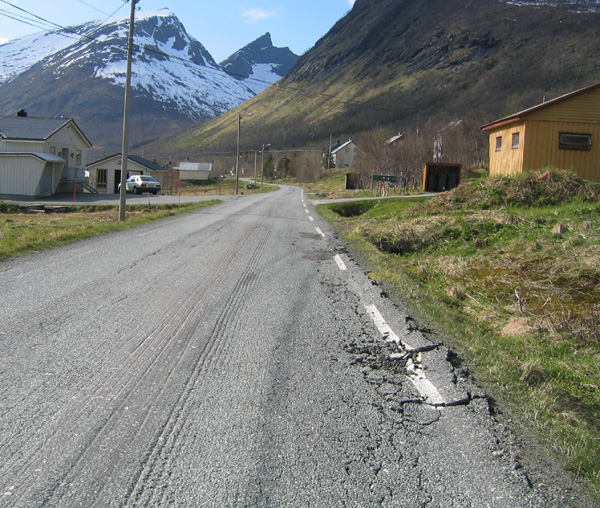
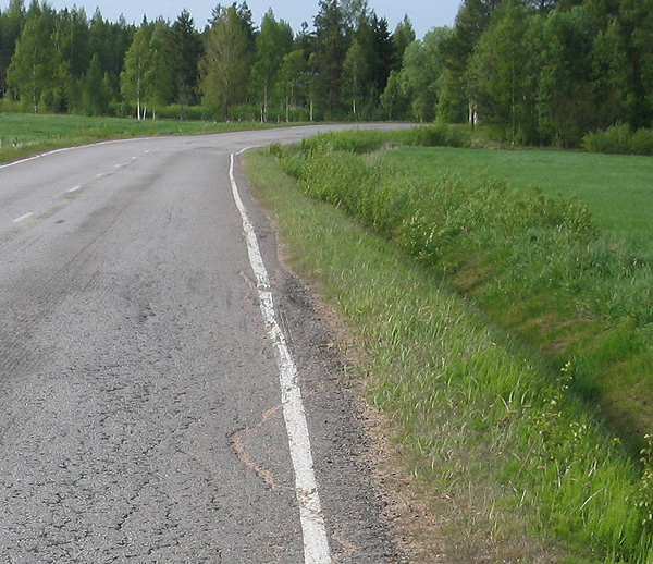
Deformation in road shoulders is a serious problem on the low volume road networks of the Northern Periphery.
This can be due to a number of reasons: a) narrow roads and inner slopes that are too steep,
b) differential frost heave and thaw settlement transversely across the road,
c) poorly constructed and/or designed road widenings and
d) poor drainage.
Strengthening of road shoulders and widening of roads require special design and construction techniques. Road widening techniques and techniques to strengthen the road if road widening has failed have been described in detail in ROADEX reports 1-3. A summary of these surveys and guidelines of road widening can be found on Road Widening Guidelines (pdf).
6.4.9 Special structures
Other structures, that can be recommended under the heading of “special structures”, are frost insulation structures. On low volume roads the idea is not so much to prevent frost heave, but rather to prevent the frost line from penetrating too far down into the subgrade to block the groundwater flow. Insulation structures allow groundwater to flow under the road and this can save expensive drainage solutions, especially on side sloping ground, where the bedrock is close to the surface. Insulation materials generally comprise the different types of polystyrene products and foamed class aggregate that has been successfully used in Norway.
