7.1. Design and dimensioning
7.1.1. Design process
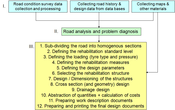
The rehabilitation design process can be divided into three phases: I. Data collection, II. Analysis and problem diagnosis and III. Design. The first two phases have been dealt with earlier in this eLearning package and this lesson will focus on phase III, the final design process.
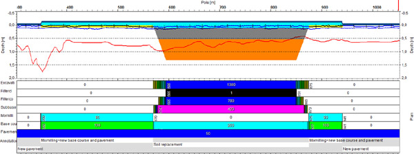
The first task in the final design process is to sub-divide the road into homogenous sections based on the road analysis and the underlying problem diagnosis. This can be a challenging task especially where the road suffers from various problems and the road topography and subgrade conditions vary significantly. It is also known that most contractors do not like to see a number of structural options in design documents but in many cases multiple measures will be the only effective solution. In the normal course of events there are usually 4-7 different types of structures in a single rehabilitation project. If there are less, it can indicate that the designer may not have fully understood the problems in place and consequently the long-term life cycle costs of the road could be expensive. The road sections should not be too short. Normally the minimum length of a homogenous section will be between 25 m and 100 m depending on the road type and class. Exceptions are “point like‟ objects like culverts and bedrock peaks.
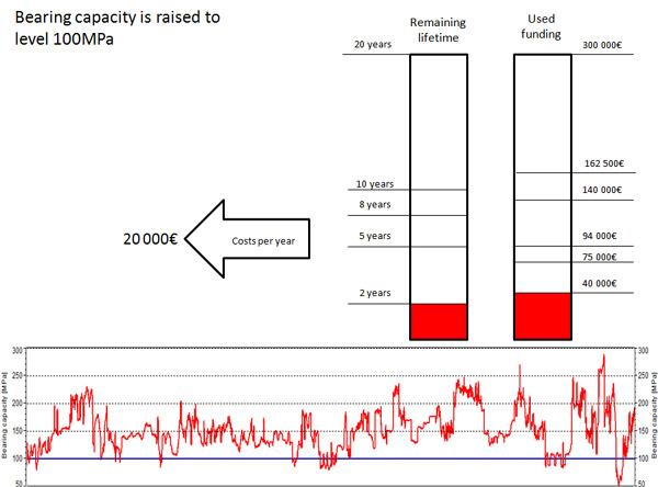
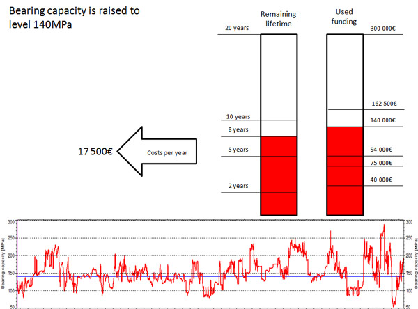
Once the road has been sub-divided into sections the next phase is to define the rehabilitation standard level. This will be governed by a number of considerations, the most important being the resources that are available, i.e. how much money can be spent on the project. The designer will have to keep this uppermost in his mind throughout the design phase and return to it regularly to control the final costs of the project. The road owner should be consulted early in this phase to agree the lifetime expectancy of the rehabilitation, i.e. whether it should be long (>20 years) or only temporary (5-7 years). If it is decided to opt for a long-term solution, but with limited money, possible solutions could include:
Rehabilitation standard level options
a) defining a minimum standard level for the rehabilitation and design for this, with any surplus money spent evenly on the rest of the road, or
b) strengthening the road starting at the weakest sections and work up to the level that funding allows.
On weak low volume roads these discussions will also have to include the level of loading on the road, i.e. if the goal is to allow year round heavy traffic on the road after the rehabilitation, if load restrictions can be applied after the rehabilitation, or if loadings and tyre pressures can be controlled. More information on this phase is given in section 6.2.4.
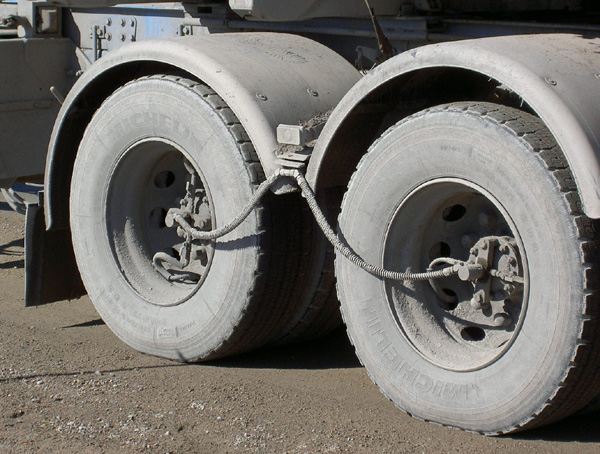
The design axle loads, tyre types and tyre pressures, as well as traffic volume (AADT) and relative share of heavy vehicles and their types, need to be defined in the design process for every road, even on unrestricted roads, as these can differ from country to country. Vehicle loadings, tyre types and tyre pressures are critical considerations when considering the lifetime of the new road against permanent deformations, particularly for weaker roads. The ROADEX design example provides information on the effects of the tyre types and pressures. View the ROADEX report: Understanding Low-Volume Pavement Response to Heavy Traffic Loading.
The next phase in the design process is the selection of the most suitable rehabilitation measures available from the “toolbox”. Problem diagnosis, and the identification of the rutting Mode, should have defined what kind of solutions should be used, but there are numerous other factors that control the selection of techniques and materials and these are discussed in detail in section 6.4.
The material parameters of the old structure and subgrade need to be identified, as well as the parameters of the new or treated materials, in order to be able to calculate the stiffness of the new structure. These parameters can be back calculated from existing information, for instance from FWD data, or DCP data, or from laboratory results. Rough evaluations of the subgrade stiffness can also be made from grain size distribution analysis, or if the subgrade soil type is known. Moduli values for the new materials also need to be known, and they can be evaluated from a) laboratory tests, b) based on their old performance (back calculated results) from some other roads, or c) from special lists of material parameters prepared by many countries for each type of material. In the case of Mode 1 rutting problems the ROADEX project is also producing material parameters that can be used in the design process (see chapter 7.1.4.3). In Scandinavia a frost design will also have to be made in addition to a design against permanent deformation, especially if the problem is Mode 2 rutting. If the road is located on a weak and compressible subgrade soil, such as peat, and the new structure will increase the stresses on the subgrade, a geotechnical design will also have to be carried out for the embankment, including appropriate stability and settlement calculations.
When the loading, road structure thicknesses, material parameters and subgrade are known, a proper rehabilitation structure can be selected from the “toolbox” for each homogenous road sections. These structures should “fit” each section and be easily constructed. The traffic management (how vehicles can use the road during the construction) should be designed at this time. An important task when selecting suitable rehabilitation structures will be to keep in mind that the new road surface level will need to be at approximately the same level as that of the next section when crossing from one section to another. Any transition structures should be also designed at this time.
Once the new rehabilitation structures have been selected for each road section, they should be checked to confirm that they will be able to resist permanent deformation. This can be done using the ROADEX design methods. Further techniques, and rules of thumb, that can be used are explained later in this lesson. If the calculations indicate that the solution will not be able to meet the recommended requirements, the thickness of the structure should be changed, or a new structural solution should be selected for the calculations.
When a potential design has been identified it is very important to check that the new solution will “fit” into the road cross section. On many occasions the available road width has been found to be too narrow to permit the existing ditches to be moved further away from the road. Similar problems can occur with new structures “on the top” that increase the height of the existing road and cause the inner slopes of the road to become too steep. Where this happens, the designer may need to change the structural solution. Sometimes it will be possible to improve the road geometry during rehabilitation projects and this can give greater flexibility to designers. In such cases, on severely damaged road sections, the best course of action can be to build a completely new road with better horizontal and vertical road geometry, or to build the new road alongside the old road (letting vehicles use the existing road during the construction). If the proposed rehabilitation increases the depths of road cuttings the design of the vertical geometry of the road may need to be reconsidered.
The road drainage should be designed at this stage, either together with the structural design and dimensioning, or after the structural solutions have been selected. A drainage design should always be carried out with a rehabilitation design. A rule of thumb is that the bottom of the ditch should be 30 cm deeper than the bottom of the road structures.
After the design and dimensioning calculations have reached a satisfactory solution the last critical phase is the abstraction of the quantities and costs. If the results of these cost calculations prove to be too high for the available funding then the design should be reviewed, in part at least, with new solutions or lower target levels, or shortening the section to be improved.
Work method statements should be made in order to avoid any misunderstandings during the construction phase. These documents should be made especially for those structural solutions that are not in everyday use in rehabilitation projects. In addition, recommendations should be given for any contingency actions that may be needed to deal with common problems, such as a risk of a “sandwich structure” being created or large boulders being found in the road structure or subgrade. Recommendations should also be offered on how to handle structures around houses and bus stops etc. should these be expected.
Finally, the designer should prepare and print the finished design documents.
7.1.2 ROADEX design method against Mode 1 rutting
One of the biggest problems in the “battle” against permanent deformation problems on low volume roads has been the lack of a design method against permanent deformation, simple enough that it could be applied in everyday projects. Based on the ROADEX laboratory test results and their analysis, as well as other recent research results, Andrew Dawson from the University of Nottingham and Pauli Kolisoja from the Tampere University have proposed a new ROADEX design technique against permanent deformation, especially against Mode 1 rutting.
The The ROADEX design method is designed especially for gravel and forest roads with a simple 2-3 layer system. A special software package had been prepared to demonstrate how the design method can be used to combat Mode 1 rutting.
The first step is to review the quality of the existing base course aggregate and any new sources of material, and identify potential poor performers. The Tube Suction test (described in chapter 4.1.10) is a simple screening tool. The next step is to assess the strength properties of the existing base course aggregate. A simplified in-situ method is proposed that uses the DCP test device (described in chapter 4.1.8). Other possible test methods are the triaxial test in the laboratory (described in chapter 4.1.10), and an indirect method of determining the aggregate strength properties using FWD data (described in chapter 4.1.9). If there is no information available about aggregate strength properties, the ROADEX project has made a list of typical strength parameters for different aggregate types that can be used in the design process.
Tyre configuration has a marked effect on the stresses in the aggregate layers, and it is therefore important to define the tyre arrangement to be used on the road. A tyre arrangement can be considered to consist of three parts; the tyre pressure (for instance 400 or 800 kPa), the tyre type (super single or dual tyres) and the radius of the contact area between tyre and road surface (this depends on the tyre pressure and the tyre type).
The strength of the subgrade aggregates is assessed using conventional geotechnical methods. The Dynamic Cone Penetrometer test is recommended as a simple, in-situ, method that gives a quick (although not very accurate) measure. The stiffness of the subgrade (Esub) can be determined for example with FWD (or LFWD) or TSD tests and indirectly based on CBR value. The shear strength of the subgrade can be estimated based on experience. This can be also done using results from DCP, CBR tests and in the case of very soft subgrade soils also with in situ shear vane test.
The required thickness of the base course (and other new structures, i.e. aggregate thickness) can be determined using local design guidelines, by the ROADEX Odemark method, or based on previous experience. It can be made also by using the ROADEX Mode 2 design method against subgrade rutting. Local experience of past conditions also needs to be taken into account, especially in areas of seasonal freezing and thawing.
General rule of thumb when designing a road against Mode1 rutting is to improve the quality of the road material by mixmilling or other mixing techniques, or by different material treatment techniques. If this is not possible then other options are either replacing the poor quality material with a better material or laying new good quality on the top. In the latter case the good quality material thickness has to be at least 20 cm. The benefit of thicker layers is that this solution improves the road structures against frost heave and Mode 2 rutting.
7.1.3 ROADEX design method against Mode 2 rutting
The ROADEX Mode 2 rutting design approach is described in detail in the following ROADEX report: Mode 2 Rutting Design Approach. The goal for the method was to find a simple method to determine the required thickness of base course aggregates and other structures to prevent weak subgrade rutting. The method that follows can be used directly in the ROADEX Partner areas of Scotland and Ireland but cannot be used in its present form in assessing the thawing time susceptibility against Mode 2 rutting.
At the moment in cases with Mode 2 rutting problems in Nordic countries ROADEX recommends using the ROADEX Odemark method, which is introduced in following chapter 7.1.4. Another method that has proven to perform well against Mode 2 rutting is a steel grid structure, that is presented in detail in chapter 7.2.3.
7.1.4 ROADEX Odemark method
A “Forest Road Rehabilitation Design procedure” has been developed as part of the ROADEX project. This method is based on the Boussinesq-Odemark dimensioning method and has been called the ROADEX Odemark method to reflect this. This method has been found suitable for forest roads and weak gravel roads, but it can also be used on low volume roads with thin pavement. The method has been tested in several rehabilitation projects in the ROADEX area. It has been proved to be a good and suitable method that permits investments (i.e. new structures) to be directed to the places that need strengthening, and the new structure thicknesses to be defined for each type of road. But the most remarkable benefit of the method is the savings in costs.
The procedure consists of six steps. The steps are:
– Step 1 – Data collection
– Step 2 – Project setup; interpretation of layer thickness
– Step 3 – Defining the layer and subgrade moduli
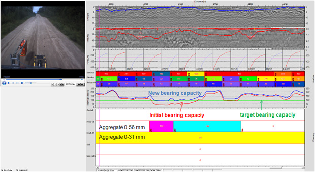
– Step 4 – Calculation of initial bearing capacity
– Step 5 – New design; designing structures to achieve the target bearing capacity
– Step 6 – Final design tuning: special design cases and drainage design
7.1.4.1 STEP 1 – DATA COLLECTION: GPR, FWD, VIDEO
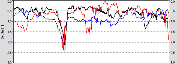
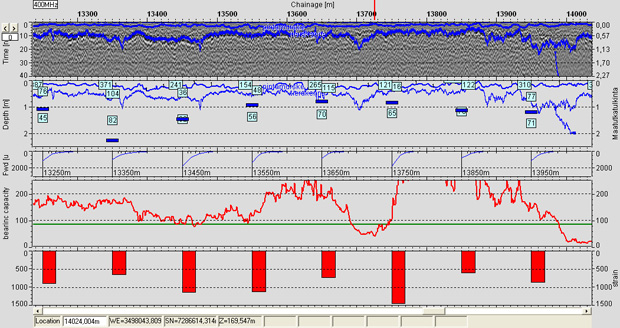
In order to be able to carry out a continuous Odemark dimensioning the road should be surveyed with GPR, to get the thickness of road structural layers, FWD, to get stiffness information, and video, to collect visual information on drainage and pavement distress etc. Good positioning of all the collected data is extremely important.
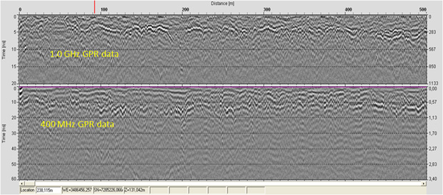
Data collection should be carried out with two different GPR antennas: a high frequency antenna (900-2500 MHz) for the top layers (wearing course, base course) and lower frequency antenna (200-500 MHz) for the overall road structures, embankments and subgrade. Usually one survey line located on the outer wheel path is enough for a typical narrow forest road. Two survey lines are recommended for wider paved roads.
The coordinates of the section, as well as good quality digital video (or still images), should be collected during the survey. The coordinate information will allow the data to be produced as a map, and can be used as a common basis for any other surveys that are needed. The video is useful for drainage analysis, verge inventory, general condition evaluation, truck meeting places and inventories of junctions etc. The condition of culverts should be checked at this time. A falling weight deflectometer (FWD) survey should be carried out for the whole length of the section on the outer wheel path, at 100 m (or 50 m) intervals. The TSD technique can be also used in rehabilitation design projects, but only on paved roads.
Detailed descriptions of GPR method are given in chapter 4.1.7, video recording and GPS coordinates in chapter 4.1.2, and the FWD method in chapter 4.1.9.
7.1.4.2 STEP 2 – PROJECT SETUP; INTERPRETATION OF LAYER THICKNESS
The project should be setup based on the GPS length if there is no other information available. The survey lengths should be scaled if needed. The preliminary data check should give enough information to choose the sampling points. Usually 1-2 base course samples per 5 km should provide the needed reference thickness information for a reliable GPR interpretation, as well as providing enough information on the quality of road materials.
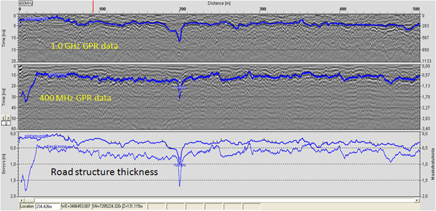
In the GPR interpretation the wearing course + base course or pavement + base course is interpreted from the high frequency antenna. This is sometimes difficult in gravel roads due to old structures, and often there is not a clear wearing course in forest roads, only a road structure. If so, this layer should be left out of the calculations for layer moduli and a very simple 2-layer model (subgrade + road structure) should be used in the Odemark design. The overall structure thicknesses are interpreted from the lower frequency antenna. It is sometimes also useful to interpret the embankment at this time. The culverts should be marked in the data (by using information held in the culvert inventory if this is available).
.
The subgrade type should be estimated from the FWD and GPR data. The minimum for this is to identify the possible peat and bedrock sections as this will be needed in Step 6.
It is possible to locate sections with unsatisfactory bearing capacity using FWD data analysis methods and index calculations. The SCI (surface curvature index) has proven to be a good index for Mode 1 rutting risk, and the BCI (base curvature index) for Mode 2 rutting risk. BCI and SCI are described in detail in chapter 4.1.9.
7.1.4.3 Step 3 – LAYER AND SUBGRADE MODULI CALCULATIONS
Once the road structure thicknesses have been interpreted, the layer moduli values and subgrade moduli can be calculated using the FWD data available. This can be done by either back calculation software packages or forward calculations algorithms (e.g. the FHWA formulas). In addition, so called Swedish Bearing Capacity formulas have been proven to provide very reliable values for subgrade moduli (Eu). Great care has to be taken at this stage to avoid the use of too high or too low moduli values in calculations. If these values are found to be out of the range the GPR layer interpretation should be checked to see if it is correct. The following table provides a rough range of reasonable moduli values that can be expected to result from the moduli calculations in low volume roads, and used in ROADEX Odemark dimensioning:
Material weak – strong
Asphalt 1000 – 5000 MPa
Other bituminous layers 700 – 3000 MPa
Unbound base course 80 – 400 MPa
Other unbound layers 40 – 200 MPa
Subgrade soil 5 – 150 MPa
Back calculation can also show those places where bedrock is close to the road surface. In these places the E2 (bearing capacity in road surface) values are almost always high indicating good bearing capacity, but there might be still a big risk for Mode 1 rutting problems in road structures. In addition, soft subgrade sections can be verified from the GPR data based on subgrade moduli values.
After the layer and subgrade moduli values have been calculated they can be transferred to the design software and the road sectioned for the design process. This means that the road should be classified into homogenous sections based on the GPR-data and video. In practice this means that the initial 50/100 m sections are shortened or lengthened according to the collected GPR data and video information.
7.1.4.4 Step 4 – CALCULATION OF INITIAL BEARING CAPACITY
The initial bearing capacity can now be calculated using the so called Odemark formula and method, which is still widely used in many countries for road structural design. The basic theory can be summarised as follows (see also the ROADEX stress and strain demo).
Both the layer thickness and the modulus affect the increase of bearing capacity on the top of a structural layer compared to the bearing capacity beneath the layer. Thus the bearing capacity on the top of the pavement structure is determined by the properties of the subgrade and each individual layer above the subgrade. The Odemark formula is a simple method for determining the overall stiffness (bearing capacity) of a layered structure, but it does not take loading into account.
The bearing capacity is calculated only on the basis of the thickness and the modulus of the layer.
The formula does however provide an easy way to determine if the structure stiffness is adequate for the loads on the road. The formula is:

The bearing capacity on the top of the layer (EP) being dimensioned depends on the bearing capacity of the layer beneath the layer being dimensioned (EA), the elastic modulus of the layer being dimensioned (E) and thickness of the layer being dimensioned (h).
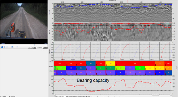
The Odemark bearing capacity information can be then presented as maps which can clearly indicate the weak sections over the road length.
7.1.4.5 STEP 5 – NEW DESIGN; DESIGNING STRUCTURES TO MEET TARGET BEARING CAPACITY
A new design is normally started by defining a target bearing capacity for the road. This target bearing capacity should be decided on a case by case basis depending on, for example, the amount of daily heavy traffic and if road is to be used by heavy vehicles throughout the year (i.e. no load restrictions). The Odemark dimensioning method allows layers to be removed, added and treated. Software packages, such as Road Doctor designer, can test different design options to identify the most beneficial design for each section of the road.
In certain cases, for instance where the road section has Mode 1 rutting problems and a thick pavement, the calculated bearing capacity of the new structure might be lower than the old structure, and still be stronger against permanent deformation. Also if the calculated initial moduli value of the base course (Mode 1 rutting) or the subgrade soil (Mode 2 rutting) is relatively high and there is evidence of rutting, these values can be lowered to better simulate the stiffness of the material during spring thaw weakening period.
7.1.4.6 STEP 6 – CHECKING THE DESIGN
There are some exceptions, which should be known when designing a road using the Odemark method: If bedrock is close to the road surface (< 2m) Odemark calculations often give high initial bearing capacities that can result in dimensioning weak road structures. Thicker and/or stiffer structures should be designed if there is evidence of Mode 1 rutting in the road. This diagnosis can be checked with the “strain” value (E_a). If the “strain” value is high, the solution is to increase thickness.
If the subgrade soil is peat Odemark calculations often give values that are too low which lead to thicker structures than are actually needed. Peat sections should be evaluated on a case-by-case basis, and good working structural solutions are given earlier in this eLearning lesson. The ROADEX eLearning lesson for roads on peat provides some useful hints and solutions for road structures built on peat.
If the drainage system of the road is in very poor shape, and the measured moduli values are low, Odemark calculations can often suggest that thick structures are required. However if the road drainage is also improved at the same time, or even earlier, and planned to be kept in better shape, the design of the surface bearing capacity can be set slightly lower than the target bearing capacity, e.g. by 10-20 MPa.
The bearing capacity analysis can provide more information for more detailed and improved design. One of the most useful parameters that can be obtained is the strain value (E_a) calculated using the Swedish bearing capacity indexes. This was designed to describe the horizontal strain at the bottom of the pavement, but it can be used as a rough index tool to estimate the risk for Mode 1 rutting on a gravel road. The higher the strain value, the higher the risk of Mode 1 rutting. When high values appear, thicker structure layers should be considered, or the layer stiffness improved by improving material quality, even if the bearing capacity is already sufficient.
Analysis of video recordings of the road, together with maps, can give useful information on the locations of junctions and meeting places that can help avoid difficulties with elevated sections of road surface. Analysis of video recordings can also help estimate the need for drainage improvements and the need to improve visibility.
The GPS coordinates can be used as a rough tool to display the geometry of the road. Adding in the elevation of the survey line can produce a quick long section of the road that can be used as a support for some decisions. The GPR horn antenna bouncing (or elevation) data is useful in estimating the roughness of the surface.
Analysing all the data at the same time using integrated analysis produces the best and most cost-effective design for the road section. It means that the parts of the road that only need a light design, or no improvement at all, will only be designed light, and the really weak sections will get appropriate strengthening to make them strong enough to meet the demands placed on them.
7.2 DESIGN ISSUES WITH PAVED ROADS
7.2.1. General
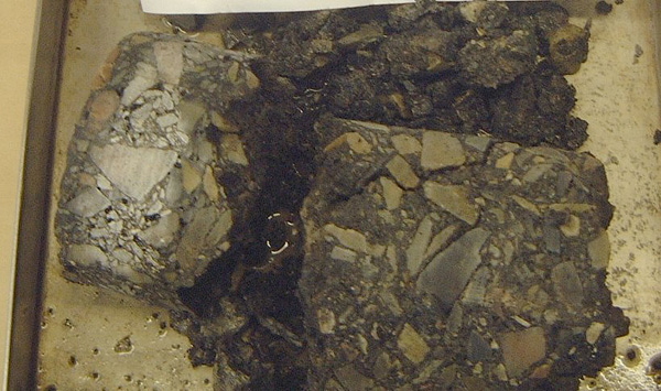
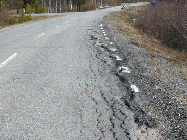
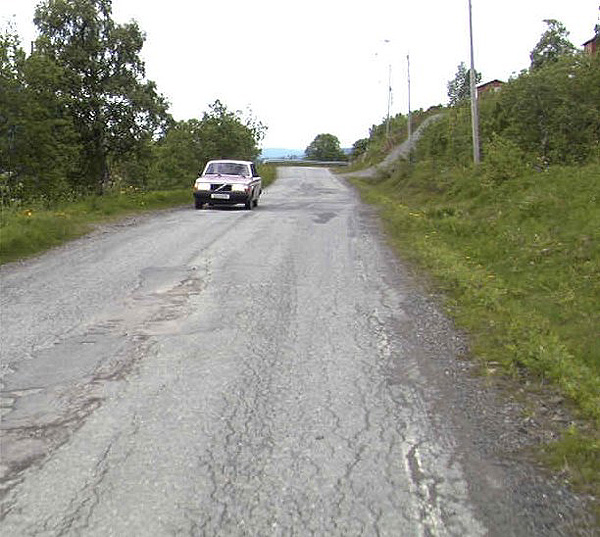
A key issue in the design against permanent deformation on paved roads is the thickness and condition of the bituminous layers above the unbound base course. Pavement contractors report that incorrect or missing thickness information regularly causes ridiculous structural solutions to be proposed, such as a 120 mm thick stabilisation on a road section where the thickness of the pavement is 160 – 180 mm. For this reason, the thickness of the bituminous layers should always be measured with GPR or by drill cores when selecting a rehabilitation method, and the nature of the problem should be classified by pavement damage type. If permanent deformation is involved the rutting mode should also be understood.
7.2.2 Design against Mode 1 rutting
The thickness of the existing pavement is one of the key parameters that need to be kept in mind when selecting a rehabilitation solution against Mode 1 rutting due to poor-quality base course. The design procedure for paved roads can be slightly complex and a few “rules of thumb‟ are offered. Firstly, the results from the ROADEX II project have shown that a 200 mm thick bound layer can reduce principal stresses to a level where no permanent deformation should take place. A second “rule‟ is that old poor-quality base should not be left within a depth of 100 – 150 mm from the new road structure. This means that the basic options are either to treat the existing base layer, or add new and stiffer layers on the top of the existing structure.
Thin pavements, 20-100 mm: If the pavement thickness is thin, all of the structural options mentioned in chapter 6.4 can be used, and the best option should be decided on a case-by-case basis. However, if the problems are only related to Mode 1 rutting, the best and most sustainable option will be stabilisation or treatment of the old poor-quality base course. Leaving this base course in place, even at deeper levels, may cause problems later. Methods that can be used for strengthening in cases when the existing bound pavement is thin (not more than 100 mm) are described in the following table:
Strengthening options for Mode 1 rutting (thin pavements 20 – 100 mm)
1. Pavement removal + new aggregate + new pavement
2. Mixmilling + new pavement
3 .Mixmilling + new aggregate + new pavement
4. Mixmilling + new aggregate + mixmilling + new pavement
5. New aggregate + mixmilling + new pavement
6. Remix stabilisation + new pavement
7. Pavement removal + bitumen stabilisation + new pavement
8. Pavement removal + new treatment agent stabilisation + new pavement
9. Soil replacement structure
10. Pavement removal + new aggregate + steel grid + new aggregate + new pavement
Thick pavements, 100-200 mm: If the pavement is 100–140 mm thick, and is not damaged seriously (only rutting), the optimum rehabilitation solution could be to mill the road surface to a proper shape and place a thicker overlay on the top of the existing pavement.

If pavement thickness is more than 200 mm then there is most likely to be severe problems with the existing pavement, or the problem is not permanent deformation.
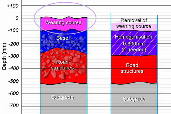
If a thick pavement is in very bad shape a good option is homogenisation, the mixing of the existing pavement with the unbound base (mixmilling). Another option is to mill out the old pavement and re-use it in a new recycled asphalt or bound base. A third, and a recommended option for thick and damaged pavements over a bad quality base, is to mill out the top 50 – 100 mm of the pavement and to leave 50 – 80 mm old pavement in place. This part can then be mixed with the poor-quality base (mixing thickness 120 – 160 mm) using the remix stabilisation technique. A new wearing course can then be placed on top. This solution treats the top part of the old poor-quality base and provides approximately 200 mm of thick bound layers that are strong enough to prevent future rutting.

7.2.3 Design against Mode 2 rutting
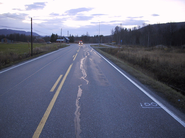
If the main problem on the road is Mode 2 rutting the best rehabilitation solution is to raise the grade line and improve the drainage. If this is not possible a second option is to try to stiffen the top layer so that it becomes sufficiently stiff that it reduces stresses in the road structure / subgrade interface to a level that permanent deformation will not take place.
However, especially in Scandinavia where frost penetrates to subgrade soil, this is much easier said than done, because frost action should be also considered.
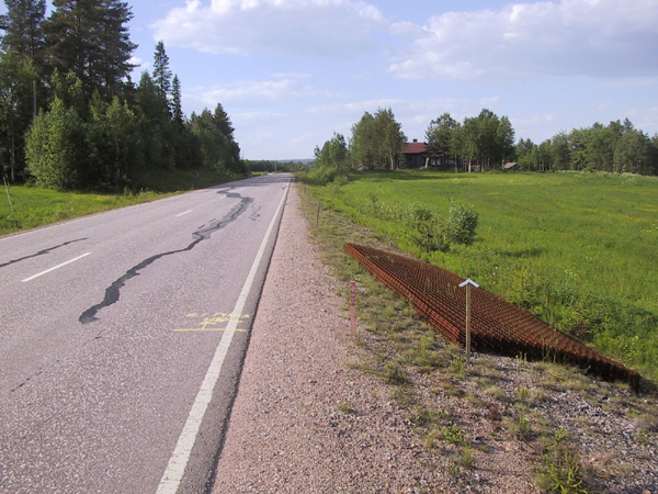
Another technique that can be recommended to prevent Mode 2 rutting on paved roads is the use of steel grids. If the pavement is thin the steel grid should be placed in the base course, roughly 250 mm from the new pavement surface.
If the pavement is thicker than 100 mm, the steel grid can be placed inside the bituminous layers. However, to prevent Mode 2 rutting it should be at least 120-150 mm deep from the new pavement surface (absolute minimum depth is 100 mm).
One advantage of the steel reinforcement is that it can also prevent the road from widening during Mode 2 rutting through the spring thaw period. In addition, in Finland, steel grids are often allowed to give 10-20 MPa extra bearing capacity in Odemark calculations.
One problem in designing against Mode 2 rutting is to define how thick the new layers should be on top of the old structure. The ROADEX design method will provide information and ideas for the solutions for different types of axle loads and road structures, but at the moment it is especially suited to weak forest and gravel roads.
Another suitable dimensioning method against Mode 2 permanent deformation is the Odemark method – with the exception that the method does not always work well on a peat subgrade. This method additionally requires thickness (GPR, test pits) and stiffness information (FWD, LWD, DCP) as design input data. On paved low volume roads, the target Odemark bearing capacity, measured on the top of the pavement, should be 160 – 200 MPa based on the road type. On the weakest paved roads, the absolute minimum design Odemark surface bearing capacity after rehabilitation should be 120 MPa. Road sections with Odemark bearing capacity values lower than this have proven to quickly fail.
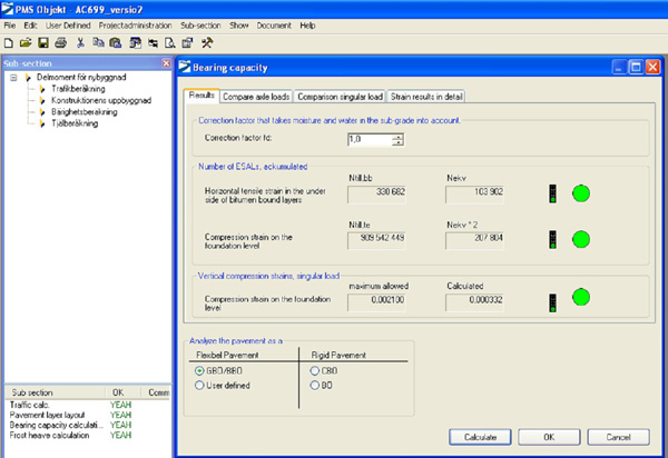
The third design method that has proven to work well against Mode 2 rutting on more heavily trafficked roads is the Swedish Road Administration “PMS Object design” method and software. This method is easy to learn and easy to use for less experienced pavement designers.
7.2.4. Special issues in design and construction process
Designing and strengthening paved roads with Mode 1 and Mode 2 permanent deformation problems have some special issues that should be kept in mind during the design and construction process.
In Scandinavian low volume roads, the most important issue is differential frost heave and thaw settlement in the longitudinal and transverse directions of the road. When these frost problems are severe a frost design should be carried out.
One rough “rule of thumb” is that if the frost heave is less than 100 mm, frost can be ignored in the design, especially when the structures will be improved anyway.
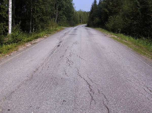
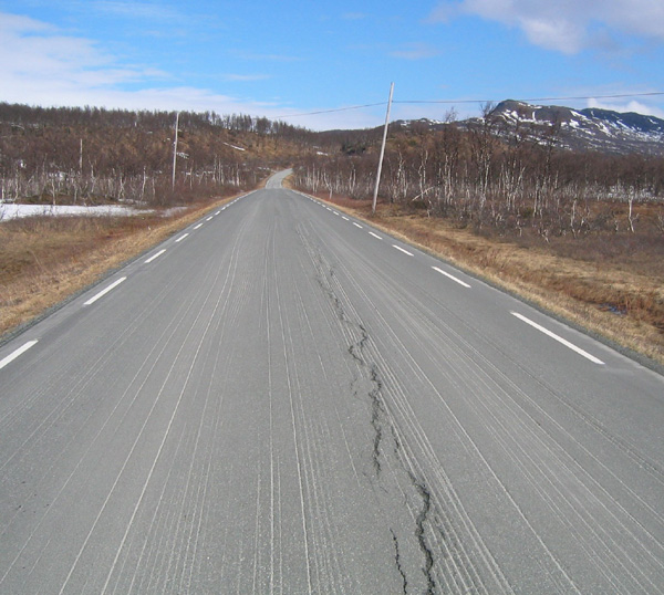
If the road has longitudinal frost cracks and medium permanent deformation problems, it is likely that the frost heave is around 100 – 200 mm, and some action should be taken (steel grids, much thicker structures, homogenisation, special drainage structures, etc).
If the frost heave is greater than 200 mm on paved roads, the road will have severe unevenness problems in addition to frost cracking. In this case the main design issue should be the design against frost action, and this design should also solve the permanent deformation problems. A demonstration of how to evaluate frost heave on the basis of annual cumulative frost hours, road structure thickness and subgrade frost susceptibility is presented in the ROADEX eLearning lesson on drainage.
A further problem that needs to be considered when strengthening paved roads is reflection cracking. In the case of old thick pavements suffering from reflection cracking the standard design against permanent deformation might not be as effective as normal, and cracks may appear soon after rehabilitation (especially if the road drainage has not been improved at the same time). This type of problem has to be resolved on a case-by-case basis.
A main reason for reflection cracking is a poorly constructed road widening. In many strengthening projects the paved road has to be widened also and this raises several new design problems and issues that are not covered in this eLearning package. However, one mistake, and the most typical, that causes reflection cracking is constructing the widening joint in the base course and subbase exactly below the outer wheel path. Where this is done reflection cracks will appear immediately on the pavement surface. The ROADEX IV project carried out research into road widening problems and how to prevent and repair reflection cracking. These results have been presented in ROADEX report.
Pavement failures can sometimes be related to severe disintegration of the bituminous layers (stripping) due to poor drainage below the layers. This is especially the case in thicker pavements. High amounts of water under the bituminous layers can give rise to high hydraulic pressures in the layers under the action of heavy traffic, especially during thawing periods. These problems can also be related to pumping, as discussed to in lesson 3.8. In such cases the only solution is to improve the drainage, mill out the bituminous layers, place a water permeable aggregate layer on the prepared surface (macadam or open graded base) and finish with a new overlay.
And, as stated several times previously, steel grids are also good at preventing pumping problems.
And, as already mentioned previously, steel grids are also good at preventing pumping problems.
7.3 GRAVEL ROADS AND FOREST ROADS
7.3.1. General
Design against permanent deformation on gravel and forest roads is an easier and more straightforward method than with paved roads as there are no stiff bituminous layers on top to consider.
However, when designing gravel roads the thickness of the wearing course, if it exists, should be also measured and kept in mind when designing the rehabilitation solution.
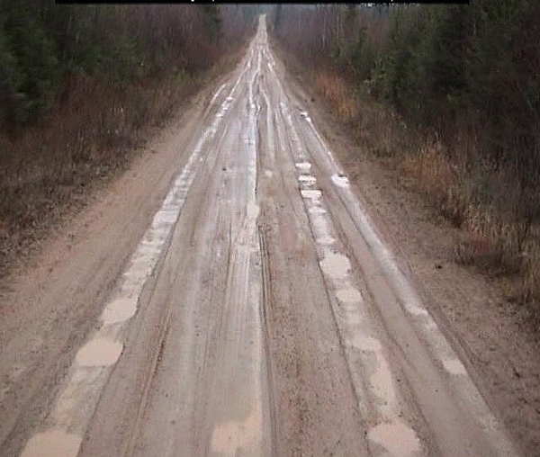
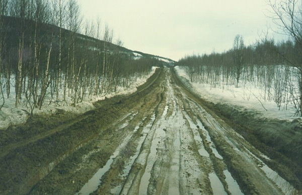
Another important thickness issue on gravel road strengthening design is that the structure thickness can vary significantly in the transverse direction due to the permanent deformation process. For instance, it is possible to have a structure thickness of 60-80 cm in the wheel paths but only 10 cm on the road shoulders and in the road centre. This should be always kept in mind during the design process and new structures should be built over a homogenised old road wherever possible.
The other critical element in the design process for gravel roads, and especially on forest roads, is the axle load and tyre type and tyre pressure. These can often be controlled, especially in timber transport projects.
A special issue on gravel roads is how to handle frost heave and spring thaw problems. This cannot be avoided on gravel roads in Scandinavia, but its effects can be minimised with good structural design and drainage management.
7.3.2. Design against Mode 1 rutting
If the problem on public gravel roads or forest roads is Mode 1 rutting the best option in most cases is laying new material on the top of the old structure. This reduces the amount of frost heave, and the new layers will be drier in the event of drainage problems. However, as mentioned earlier, the minimum layer thickness of the new layer should be 150-200 mm.
If good quality base materials are not available locally for the road, a good option is to treat the poor-quality material by coarsening it by mixing ballast with it (if this is available). The recommended solution is to use bitumen stabilisation with a low binder content, or new “non-traditional” treatment agents. All of these techniques are described in more detail in the next lesson 7.4.
Mode 1 rutting is strongly related to moisture and drainage problems and as a consequence the drainage of the road should always be improved during rehabilitation work, and proper cross fall should be ensured on the new road surface. In this regard a good cross fall in gravel roads is 4 %.
7.3.3. Design against Mode 2 rutting
The easiest design solution for gravel and forest roads with Mode 2 rutting problems is to add extra layers on the top of the old road. The biggest problem however is how to estimate the additional amount of aggregates to add.
Another option that can be employed is the Odemark method. For public gravel roads a target bearing capacity of 120 – 140 MPa should be used, for high category forest roads used year round 100 MPa should be used, and for other forest roads 80 MPa.
On weak subgrade areas with Mode 2 rutting problems it is recommended that a geotextile is incorporated to prevent the new road structures mixing with the subgrade. A steel grid should also be used if the road has
widening and/or pumping problems.
Soil replacement structures (0,4 – 0,8 m) can also provide good options, particularly where the road topography changes over short intervals.
7.3.4. Special issues in design and construction process
There are a number of special issues that need to be kept in mind when carrying out rehabilitation design and construction on gravel and forest roads. One important consideration is that the old wearing course should not be left under the old structure, especially if it is thick and has a high fines content. This layer should be taken out of the road and used as support material on the edge of the road or, alternatively, part mixed with the new wearing course material.
The biggest mistake in the design of strengthening projects on gravel roads and forest roads is to insufficiently design the new structures because of limited funding. A 10 cm thick layer of base course aggregate on the top of a gravel road suffering from permanent deformation is, in 90 % of cases, a waste of money, and problems will most likely reappear during the following spring thaw period. If the funding is not enough for the whole road, the best option is to shorten the road section to be strengthened, or to focus the strengthening work only on the weakest places.
Another important issue when planning the strengthening of gravel and forest roads is the timing of the work. If the construction work is to be carried out during the fall, when there will be high amounts of rainfall and low evaporation, other sections on the road can be expected to be damaged due to heavy lorries bringing gravel to the site. For this reason, all strengthening works should be executed during the warm summer months when the bearing capacity of the road is at its highest.
Finally, it is recommended that the drainage on the road section should be improved in the year before the strengthening works. This will make the construction work easier, with less damage.
7.4. Material treatment techniques against permanent deformation
7.4.1. General
Material treatment should be considered as a possible rehabilitation method, if the rutting mode within the road is Mode 1 and the reasons for the problems can be related to poor quality base course material (View the ROADEX II report: New Material Treatment Techniques).Material treatment can also be considered if good-quality base course material is not available locally, or the transportation distance is long, or if there are obstacles, such as a peat subgrade, that prevent the road surface to be raised.
Factors that should be considered when planning a rehabilitation project are: a) the aim of the project, b) the materials available, c) the equipment available, d) the site circumstances and logistics, such as weak bridges preventing bringing the machinery to the site, e) the frost response of the road and f) the likely costs of the project.
In addition to these considerations, attention should also be paid to the condition of the drainage, as water in the road structures can also weaken the stabilised structure.
Finally, as with all solutions, the finished treated structure should be designed to be capable of carrying the required design load.
7.4.2 Treatment agents
Treatment agents can, in general, be classified as traditional treatment agents and non-traditional agents.
Traditional treatment agents
The recognised traditional treatment agents are bitumen, slag, cement and different combinations of them.
Bitumen and cement are the most common stabilisation agents for bearing capacity improvements on road structures. Bitumen has also been used for moisture susceptible materials in seasonal frost areas when cement stabilisation cannot be recommended due to the risk of differential frost heave in the road.
There is a range of reliable national guidelines available for rehabilitation design using traditional stabilisation agents that are based both on long-term experience and research.
Bitumen
Today bitumen is the most popular agent when improving the technical properties of the base course materials. Bitumen stabilisation is made by using either foamed or emulsified bitumen that is mixed with the material to be treated. Experience from Sweden and Norway, reported in the ROADEX I project, indicates that foam bitumen binds the fines slightly better than emulsified bitumen. Based on these findings the following recommendations can be made for choosing a bitumen stabilisation technique:
– If the fines content is less than 8 %, stabilisation with emulsified bitumen gives best results.
– Foamed bitumen should be used where the fines content is more than 12 %.
– If the fines content is between 8 – 12 %, both treatments are equally suitable and the type of bitumen depends on the price.
“Remixer” stabilisation is a method where bitumen is used as the aggregate binder, and the old pavement is heated and mixed into the new structure. The remixer method is presented in greater detail in 7.4.3 Treatment techniques.
Now, in 2020´s, when bitumen stabilisation has been used for 20-30 years, experiences of the long term performance of these treatments can be seen. According to data from the PEHKO project in Finland, the homogeneity of the stabilized structures could have been better in the old roads. In one example, part of the stabilized section had performed very well with time, whilst another part of the stabilized material had badly disintegrated. The main reason for the problems might be changes in fines content and bitumen content, but high deflections due to the weak and frost susceptible subgrades most likely also had a substantial impact.
Slag
Slag is suitable as an aggregate binder if the material has a fines content of between 5-15 %. This stabilisation agent is good for projects, where there is sufficient time for the binder to react, frost heave is quite small, and there is a need for good bearing capacity.
Cement
The use of cement in stabilisation has been studied for a long time and codes of practice are available in many countries. The treatment cannot however be recommended for low volume roads, especially those in seasonal frost areas. A cement stabilised base courses is stiff and cracks easily in response to differential frost heave. Subgrade soils need to be non-frost susceptible for cement to be effective as a stabilisation agent.
Composite
Bitumen and hydraulic binders can be used together as an aggregate binder in composite stabilisation and the composite stabilised structure created is often called a “semi-rigid‟ structure. Composite stabilisation is at its best when faster curing than bitumen alone is required, for example on roads with high traffic volumes, and thus it is not a common method on low-volume roads. As with cement stabilisation, composite stabilisation can only be recommended for low-volume roads where the subgrade soil is non-frost susceptible.
New, non-traditional treatment agents
Today there are many types of non-traditional stabilisation agents available but until recently these treatment agents have not been classified. The classifications that have been made have been compromised differences in local practices and experiences based primarily on dust-suppression or on stabilisation of subgrade materials. In the ROADEX project non-traditional stabilisation agents have been classified into the following classes: a) polymers, b) enzymes, c) ionic treatment agents, d) lignins, e) resins, f) combined products and g) other types of stabilisers.
Polymers
Polymers can be developed in very many different forms. Acrylic polymers, for instance, strengthen as they dry. They develop a chemical adhesion that binds and holds the particles together. However, at least one polymer product has been reported as having enzymatic effects. One of the polymer products potentially applicable in stabilising coarse-grained materials is polymer-coated fly ash, which is used in the form of powder and may also contain lime. It is likely that, in the future, the assortment of available polymers will increase and the areas of application will be more diversified. This would require that a more detailed sub-division of the polymer products be made.
Polymers are available in many different types and when in the emulsion form, they are usually fairly easy to use. An emulsion normally contains 40 to 50 % of polymer, 1 to 2 % of emulsifying agent while the rest is water. Most of the polymer products intended for stabilisation are vinyl acetates or acrylic copolymers.
Enzymes
The basic structure of enzymes consists of proteins which in biological systems act as catalysts. If a soil is to be stabilised with enzymes there should be a lot of silt and clay sized particles and organic material. Enzymes that have been added to a soil material remain continuously reactive. The enzymes are very specific in synthesising certain groups of chemical compounds and limiting their action to specific bonds in the compounds with which they react. When the enzymes contained in a treatment agent have been mixed with water and spread into the soil they can act in many different ways. The reaction can include breaking of the clay lattice and combining of cations and other compounds with the aid of organic molecules. Breaking of the lattice decreases the grain size of clay particles and helps them to combine with organic materials. Compaction is a very important issue in the use of enzymatic treatment agents.
Because the use of enzymes requires a significant quantity of fines, they are usually not applicable for base materials containing less than 20 % of fines. According to several sources enzymes require a relatively long curing period, which can also hinder a more widespread use of the enzymatic treatment agents in the Northern Periphery areas when the weather conditions are often rainy and wet.
Ionic treatment agents
The electrolytes contained in ionic treatment agents affect the basic nature of clay minerals. In soil materials with normal moisture content the electrolytes are transported by osmosis. They release the adsorbed water and coagulate as a dense moisture-free mass. According to the information provided by the manufacturers ionic treatment agents are only effective if the fines content is at least 35 % and a certain proportion of the fines must be clay minerals. After stabilisation and compaction, drying-wetting and freeze-thaw cycles should have no effect on the treated soil material. Treatment with an ionic stabiliser should be done when the soil material is at optimum water content or near full saturation. If the treatment is done by scarifying, a very slippery surface will form which requires a friction layer. Deep treatments can be made below the ground surface through an injection method.
Many of the sulphonated oils can be included in the ionic category. Acids are used as a reactant in many of the ionic treatment agents.
Lignins
Lignin types of products are often made of by-products from the forest industry. They are generally used as dust suppressants. However, lignosulphonate, for instance, provided good short-term bearing capacity in some test series but the treatment agent was water-soluble. On the other hand, in another research project the optimum amount, 5 % of lignosulphonate, proved to give good water-protection properties in silty sand. Consequently, lignin products could, in some cases, be used to stabilise, for instance, forest roads for temporary use. Lignin has proved to work well also on the ROADEX II test section in Ängesby, Sweden, where an old and badly deteriorated paved road was turned back to a gravel road and the base course was stabilised with lignin.
Resins
The resins category contains a wide range of products. In terms of the mechanisms of effect, a common feature of the resins group is that they coat and bind the fines. Some of the resins may also form a hydrophobic surface as they coat the fines. In laboratory tests made in the Tampere University of Technology in Finland some resins have proven to work very well to improve the base material quality. Part of the treatment agents are natural products which mean that some of the materials are biodegradable and, as such, have a fairly short-term effect. On the other hand, the oil resin products from this group may pose low environmental risks if some of the material is inadvertently released into water systems during a treatment.
Combined products
The combined products group consists of treatment agents that combine at least two clearly different constituents none of which can be considered more important than the others.
Other types of stabilisers
This group contains the products that cannot be classified into any of the above-mentioned groups. They are mainly materials used as dust suppressants or materials with very marginal use in reducing the water suction properties of soil materials/aggregates.
7.4.3. Treatment techniques
Mixmilling
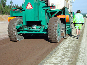
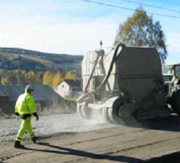
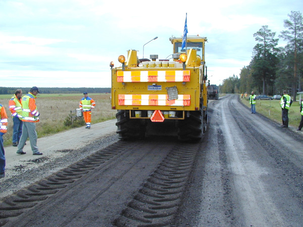
In this technique bound and unbound courses of road structure are homogenised by milling. Binders are not used. Additional aggregate can be added if the existing shape of the road or the grain size of the existing road materials needs to be amended.
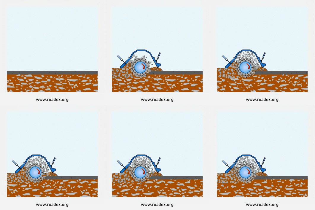
Once mixed, the mixed courses are shaped by blade grader and tamped by roller.
Mixmilling on paved roads is a very good technique where rut depths are high and the pavement is relatively thin (< 100 mm). Where a road has shoulder deformation problems the cross fall of the road can be easily reshaped after mixmilling. Mixmilling also has the benefit of slightly coarsening the base course because the old pavement is crushed and mixed into it. Old pavement material can also produce a binding effect within the mixmilled base.
Coarsening
In coarsening, some coarse-grained aggregate, for example open graded base or ballast, is mixed into the existing road structure to improve its grading. Coarse aggregates are spread on the road and mixed by miller. Mixed courses are shaped by a blade grader and tamped by a roller. Coarsening can be a very good option on gravel roads with a high fines wearing course and with surface thaw weakening problems during the spring thaw period.
Stabilisation
Stabilisation of a base course means that only the unbound base course is treated. So, if a road has a pavement it has to be milled away first. Stabilisation can be carried out in-situ or by “plant stabilisation‟. In the rural areas of the Northern Periphery in-situ stabilisation is the most popular choice.
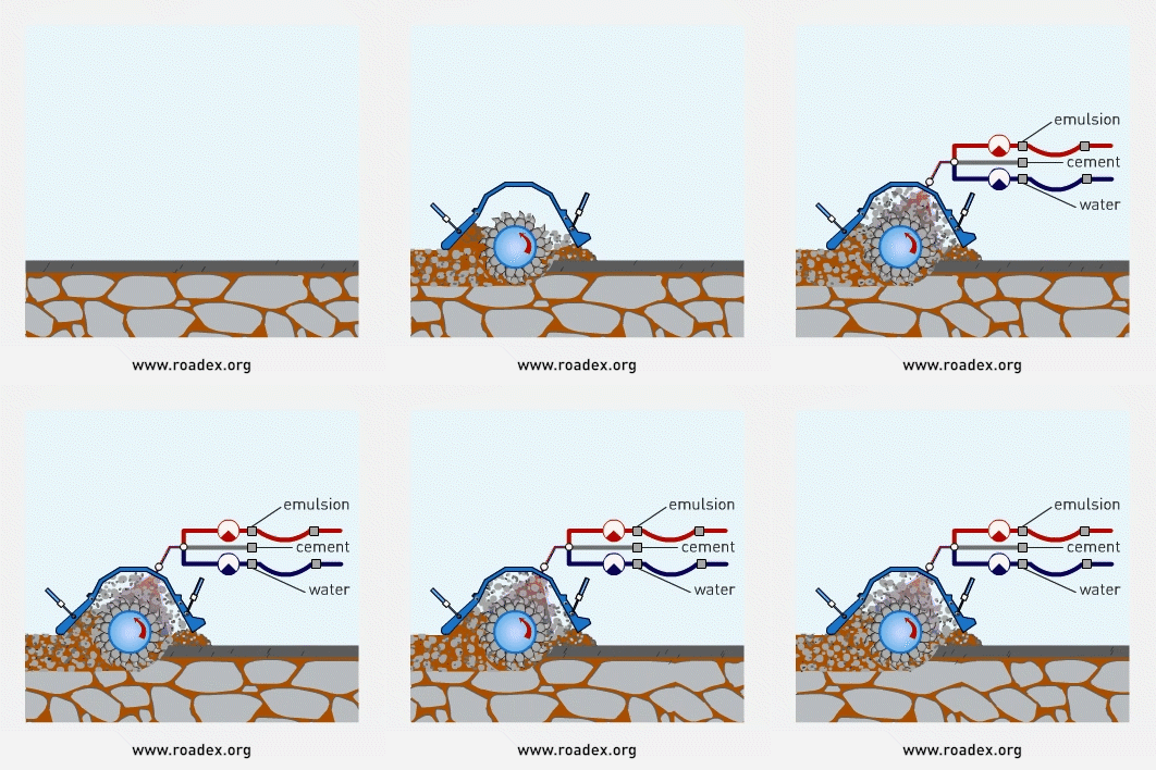
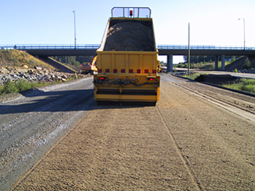
In-situ stabilisation mixes the aggregate binder with the top part of the pavement structure within an optimum water content. In the “plant stabilisation‟ method the stabilised mass is prepared in central mixer station. In this method the stabilised mass is normally spread using an asphalt paver. The stabilised course is compacted by a roller. Finally, a new wearing course is laid over the stabilised course.
Remixer
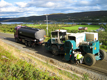
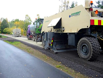
Remixer stabilisation is a “mix-in-place‟ method which is used in particular to repair paved roads that are already cracked and have lost or are losing their bearing capacity. Remixer stabilisation is made by mixing the old, heated pavement with the upper part of the base course, and adding new bitumen binder with additional new aggregate where necessary, resulting in a bitumen-stabilised layer. Remixer stabilisation can offer remarkable savings. Remixer stabilisation has the same traffic disturbance as a normal pavement rehabilitation.
7.4.4. Laboratory testing method
When planning a stabilisation process, the properties of the old road structure should be known, for example, the thickness of the base course. If the road is paved and the pavement is to be mixed into new structure, the thickness of pavement and any variations in thickness should be identified, for example by ground penetrating radar. The recommended laboratory tests for problematic materials in road structures are presented in chapter 4.1.9. Using these tests it should be possible to select the most appropriate treatment agent and method.
Results from tests help to choose the most appropriate treatment agent.
7.4.5. Proportioning the amount of treatment agent
Selecting the proportion of treatment agent for a project will depend on the properties of the existing road structure material, especially the grain size distribution curve and the properties of the fines.
The residual bitumen content for bitumen stabilisation is usually 3-4 % but good results have been gained by adding only 1 % bitumen to the base course. The actual bitumen content to be used will depend mainly on the fines content. A rough estimation of the bitumen content necessary can be calculated using equation:
Bitumen content= 0.14* fines content (<0.063mm, %)+2.6.
Residual bitumen content for the remixer-method is usually 3-3.5%. In composite stabilisation the same principles as bitumen stabilisation can be used.
Non-traditional stabilisation agents should be proportioned using the instructions provided by the manufacturers.
